Epyon
Well-known member
Work in progress: Industrial Teensy
We often use Teensies for measurement and monitoring applications in industrial environments. Mostly these are small batch projects for which we use circuits on perfboard and aluminum enclosures (we once ordered way too many of them for another project and have them now lying around ).
).
This year I used the slow summer months to design a more professional setup. The main qualifiers were: cost-efficient, robust, industrial standard inputs, compact and standardised form factor and flexible expansion options.
So now I present you a sneak peek at my industrial Teensy setup .
.

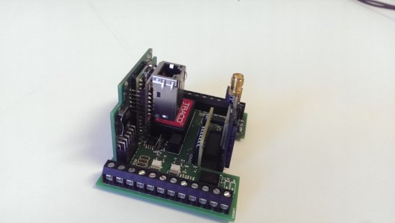
It consists out of three boards:
There is an ATtiny45 on the baseboard, programmable through the ICSP pads visible on the photo. It’s connected to a MOSFET switch that can cut power to the entire unit (the ATtiny itself is powered prior to this switch) and to one of the digital pins of the Teensy. I use it as watchdog/supervisor. If anything goes south (e.g. one of the communication processors hangs) it can restart the entire unit if needed. You could also use it to power down the unit. There is a jumper to bypass this altogether.
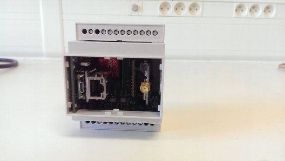
The MCU board houses, of course, the Teensy. It has all the side pins brought out, and also an additional 6 pins on the back (Serial3 and the pins surrounding it). The USB connector is accessible from the front of the enclosure.
Under the Teensy is the SD card interface, also accessible from the front. On top of the Teensy is the Wiz820io Ethernet interface. The MCU board has an additional 3.3V regulator to provide enough juice to the Wiznet. You can bypass this regulator through a jumper and use the Teensy regulator if you don’t need it.
There is a 12mm battery holder connected to Vbat to maintain the Teensy RTC. There is one power led and two status leds connected to Teensy pins, viewable through the front panel.
You can plug in an optional communications board that connects to Serial1. Right now we have support for:


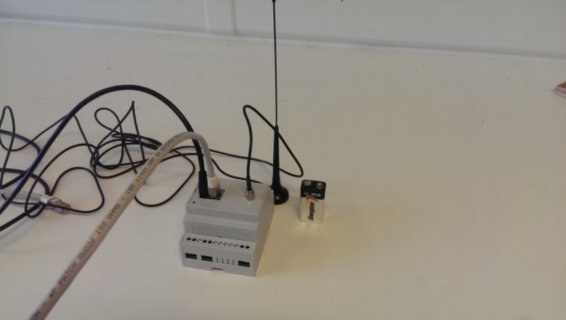
The enclosure is DIN rail mountable and takes up the width of 4 DIN modules. All external I/O is accessible through screw connections.
Currently, I’m making some small revisions to the MCU board:
 .
.
We often use Teensies for measurement and monitoring applications in industrial environments. Mostly these are small batch projects for which we use circuits on perfboard and aluminum enclosures (we once ordered way too many of them for another project and have them now lying around
This year I used the slow summer months to design a more professional setup. The main qualifiers were: cost-efficient, robust, industrial standard inputs, compact and standardised form factor and flexible expansion options.
So now I present you a sneak peek at my industrial Teensy setup

It consists out of three boards:
- Baseboard containing power supplies, I/O interfaces, MCU supervisor (ATtiny45) and diagnostic leds (for I/O and power)
- MCU board with the Teensy, SD card, Wiz820io Ethernet interface, 3.3V regulator, RTC battery and diagnostic leds (for MCU activity) that stacks on the baseboard
- Optional communications board that also stacks on the baseboard on the other side
- 4x 5V to 24V level optically isolated digital inputs that lead to Teensy digital pins
- 3x 0-10V RSE analog inputs (buffered with unity gain opamps) through optically isolated ADS1115 ADC (I2C)
- 1x 0-20mA analog input (also on the ADS1115)
- 1x galvanically isolated RS-485 driver (half duplex)
- 18V to 36V power supply input (could change to 12V-36V)
- 3.3V UART (Serial3) output for debugging
There is an ATtiny45 on the baseboard, programmable through the ICSP pads visible on the photo. It’s connected to a MOSFET switch that can cut power to the entire unit (the ATtiny itself is powered prior to this switch) and to one of the digital pins of the Teensy. I use it as watchdog/supervisor. If anything goes south (e.g. one of the communication processors hangs) it can restart the entire unit if needed. You could also use it to power down the unit. There is a jumper to bypass this altogether.
The MCU board houses, of course, the Teensy. It has all the side pins brought out, and also an additional 6 pins on the back (Serial3 and the pins surrounding it). The USB connector is accessible from the front of the enclosure.
Under the Teensy is the SD card interface, also accessible from the front. On top of the Teensy is the Wiz820io Ethernet interface. The MCU board has an additional 3.3V regulator to provide enough juice to the Wiznet. You can bypass this regulator through a jumper and use the Teensy regulator if you don’t need it.
There is a 12mm battery holder connected to Vbat to maintain the Teensy RTC. There is one power led and two status leds connected to Teensy pins, viewable through the front panel.
You can plug in an optional communications board that connects to Serial1. Right now we have support for:
- Adafruit FONA cellular boards
- ESP8266 (custom breakout board)
- LoraWan RN2483-I (custom breakout board)


The enclosure is DIN rail mountable and takes up the width of 4 DIN modules. All external I/O is accessible through screw connections.
Currently, I’m making some small revisions to the MCU board:
- Using sockets to make the Teensy and Ethernet removable
- Adding a SPI header for later addon boards
- Front side LCD display (no room anymore)
- User configurable analog inputs (no direct need in our application)
- Digital outputs (same)
- Integrated 230V input PSU (holy declaration of conformity Batman!)

