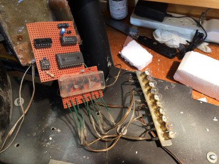
I'm building an LED bar graph type thing for the Proton Pack I built in 1984.
http://marshall-arts.net/ProtonPacks/finished.html
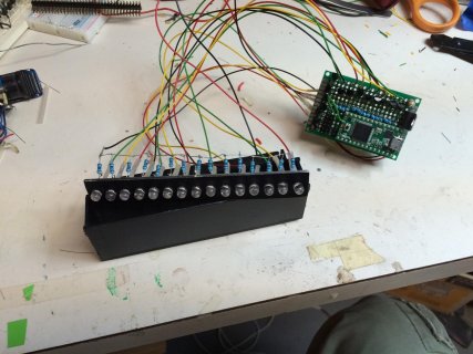
A stack of 15 LEDs grows from the bottom to top, resets, grows etc.
Three questions:
1. I was planning to repurpose code from a Ghostbusters forum that was written for a Arduino Mega Board. Will transposing the relevant pin numbers to a Teensy 3.1 be sufficient to make this work, or are there some libraries or other code that's unique to the Mega that won't work with a Teensy? (Code below-the Power Cell code is my focus for now)
2. I plan to run the system off of 4 AA batteries. I was going to use a 3.3V voltage regulator to drop that 6V down to power the Teensy via its 3.3V input (and one of the GNDs). Is that kosher?
3. I'll be connecting the Digital Write pins of the Teensy to 2N2222 NPN transistors to drive my LEDs. I've calculated the limiting resistor for the LEDs (based on their spec voltage and current draw), but do I need to insert resistors between the digital write pins of the Teensy and the base of the NPN transistors?
I hope to cobble this together by Saturday for the Rose City Comic Con.
Thanks.
Shawn
http://marshall-arts.net/ProtonPacks/finished.html
A stack of 15 LEDs grows from the bottom to top, resets, grows etc.
Three questions:
1. I was planning to repurpose code from a Ghostbusters forum that was written for a Arduino Mega Board. Will transposing the relevant pin numbers to a Teensy 3.1 be sufficient to make this work, or are there some libraries or other code that's unique to the Mega that won't work with a Teensy? (Code below-the Power Cell code is my focus for now)
2. I plan to run the system off of 4 AA batteries. I was going to use a 3.3V voltage regulator to drop that 6V down to power the Teensy via its 3.3V input (and one of the GNDs). Is that kosher?
3. I'll be connecting the Digital Write pins of the Teensy to 2N2222 NPN transistors to drive my LEDs. I've calculated the limiting resistor for the LEDs (based on their spec voltage and current draw), but do I need to insert resistors between the digital write pins of the Teensy and the base of the NPN transistors?
I hope to cobble this together by Saturday for the Rose City Comic Con.
Thanks.
Shawn
Code:
///////////////////////////////////////////////////////////////////
// Propcicle's Arduino Code for Proton Pack and Wand Lights
// Feel free to use in your pack along with an Arduino Mega Board
// Developed March 2015
///////////////////////////////////////////////////////////////////

int arrayIndex = 0; //Index variable for powercell lights
int arrayEnd = 15; //Index limiter for powercell lights
int cyclo = 1; //Index variable for cyclotron lights
int powon = 25; //LED On delay for power up sequence, recommend setting to 25
int state = 0; //state = 0 for pack off,state = 1 for startup seq,state = 2 for normal powercell cycle

// the follow variables is a long because the time, measured in miliseconds,
// will quickly become a bigger number than can be stored in an int.
unsigned long previousMillis = 0; // will store last time LED was updated
unsigned long duration = 40; // interval at which to blink (milliseconds)

void setup() {
//
pinMode(22, OUTPUT); // Power Cell LED 1 and Wand Bar LED 1
pinMode(23, OUTPUT); // Power Cell LED 2 and Wand Bar LED 2
pinMode(24, OUTPUT); // Power Cell LED 3 and Wand Bar LED 3
pinMode(25, OUTPUT); // Power Cell LED 4 and Wand Bar LED 4
pinMode(26, OUTPUT); // Power Cell LED 5 and Wand Bar LED 5
pinMode(27, OUTPUT); // Power Cell LED 6 and Wand Bar LED 6
pinMode(28, OUTPUT); // Power Cell LED 7 and Wand Bar LED 7
pinMode(29, OUTPUT); // Power Cell LED 8 and Wand Bar LED 8
pinMode(30, OUTPUT); // Power Cell LED 9 and Wand Bar LED 9
pinMode(31, OUTPUT); // Power Cell LED 10 and Wand Bar LED 10
pinMode(32, OUTPUT); // Power Cell LED 11 and Wand Bar LED 11
pinMode(33, OUTPUT); // Power Cell LED 12 and Wand Bar LED 12
pinMode(34, OUTPUT); // Power Cell LED 13
pinMode(35, OUTPUT); // Power Cell LED 14
pinMode(51, OUTPUT); // Cyclo Light LED 1
pinMode(52, OUTPUT); // Cyclo Light LED 2
pinMode(53, OUTPUT); // Cyclo Light LED 3
pinMode(50, OUTPUT); // Cyclo Light LED 4
pinMode(7, OUTPUT); // Vent Light Output
pinMode(11, OUTPUT); // Proton Stream Output
pinMode(8, INPUT); // Pack Power On - "Activate" Switch
pinMode(9, INPUT); // Vent Light On - Bottom Bar Graph Light
pinMode(10, INPUT); // Fire the stream - "Intensify" button
pinMode(40, OUTPUT); // Any wand light that should be constatnt on after startup
}

void loop()
{
// here is where you'd put code that needs to be running all the time.

// check to see if it's time to blink the LED; that is, if the
// difference between the current time and last time you blinked
// the LED is bigger than the interval at which you want to
// blink the LED.
unsigned long currentMillis;
unsigned long elapsedMillis;

//int ledon = 25; //On delay for individual light for normal powercell
//int ledoff = 250; //Off delay for bar of lights

//Code for pack on sequence
if (state == 0 && digitalRead(8) == LOW) //Initial Starting point
{
//Do nothing - all lights off
digitalWrite(22, LOW);
digitalWrite(23, LOW);
digitalWrite(24, LOW);
digitalWrite(25, LOW);
digitalWrite(26, LOW);
digitalWrite(27, LOW);
digitalWrite(28, LOW);
digitalWrite(29, LOW);
digitalWrite(30, LOW);
digitalWrite(31, LOW);
digitalWrite(32, LOW);
digitalWrite(33, LOW);
digitalWrite(34, LOW);
digitalWrite(35, LOW);
digitalWrite(51, LOW);
digitalWrite(52, LOW);
digitalWrite(53, LOW);
digitalWrite(50, LOW);
digitalWrite(40, LOW);
digitalWrite(7, LOW);
state = 0;
}

else if (digitalRead(8) == LOW) //Turn all Lights off
{
digitalWrite(22, LOW);
digitalWrite(23, LOW);
digitalWrite(24, LOW);
digitalWrite(25, LOW);
digitalWrite(26, LOW);
digitalWrite(27, LOW);
digitalWrite(28, LOW);
digitalWrite(29, LOW);
digitalWrite(30, LOW);
digitalWrite(31, LOW);
digitalWrite(32, LOW);
digitalWrite(33, LOW);
digitalWrite(34, LOW);
digitalWrite(35, LOW);
digitalWrite(51, LOW);
digitalWrite(52, LOW);
digitalWrite(53, LOW);
digitalWrite(50, LOW);
digitalWrite(40, LOW);
digitalWrite(7, LOW);
state = 0;
}

else if (state == 0 && digitalRead(8) == HIGH) //Startup Sequence
{
for (int y = 0; y < 14; y = y + 1) {

int x = 1; //Light Loop incrementor
for (int powled = 35; powled > 21 + y; powled = powled - x) {
digitalWrite(powled, HIGH);
delay(powon);
digitalWrite(powled, LOW);
}
digitalWrite(22 + y, HIGH);

}
state = 1;
}
else if (state == 1)
{
//Code for turning on the next cyclo light
digitalWrite(40, HIGH);
switch (cyclo)
{
case 1:
digitalWrite(51, HIGH);
break;
case 2:
digitalWrite(52, HIGH);
break;
case 3:
digitalWrite(53, HIGH);
break;
case 4:
digitalWrite(50, HIGH);
break;
default:
cyclo = 0;
}
//Main Code for incrementing Powercell lights
currentMillis = millis(); // capture current "time"
// all time related variable are unsigned long
elapsedMillis = currentMillis - previousMillis; // see how much time has passed
if (elapsedMillis >= duration) { // time for next occurrence of event?
previousMillis = previousMillis + duration; // set up time for next occurrence of event
arrayIndex = arrayIndex + 1; // increment pointer
if (arrayIndex == arrayEnd) {
arrayIndex = 0; // reset to beginning
digitalWrite(22, LOW);
digitalWrite(23, LOW);
digitalWrite(24, LOW);
digitalWrite(25, LOW);
digitalWrite(26, LOW);
digitalWrite(27, LOW);
digitalWrite(28, LOW);
digitalWrite(29, LOW);
digitalWrite(30, LOW);
digitalWrite(31, LOW);
digitalWrite(32, LOW);
digitalWrite(33, LOW);
digitalWrite(34, LOW);
digitalWrite(35, LOW);
//delay(40); //Optional delay before starting lights again

switch (cyclo)
{
//Code for turning off the previous cyclo light
case 1:
digitalWrite(51, LOW);
break;
case 2:
digitalWrite(52, LOW);
break;
case 3:
digitalWrite(53, LOW);
break;
case 4:
digitalWrite(50, LOW);
cyclo = 0;
break;
}

cyclo = cyclo + 1;
}

// do action based on value stored at arrayIndex
// This cycles the powercell lights
digitalWrite(21 + arrayIndex, HIGH);

} // end time check

if (state == 1 && digitalRead(9) == HIGH) //Vent Light Activation Loop
{
digitalWrite(7, HIGH);
}
else
{
digitalWrite(7, LOW);
}
if (state == 1 && digitalRead(9) && digitalRead(10) == HIGH) //Proton Stream Activation Loop
{
digitalWrite(11, HIGH);
delay(30);
digitalWrite(11, LOW);
delay(30);
}
else
{
digitalWrite(11, LOW);
}

} // end loop

}