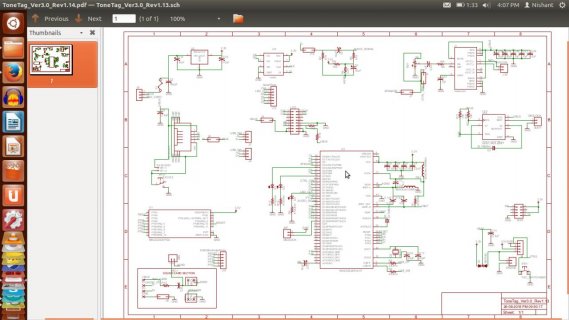
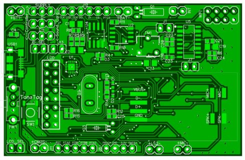
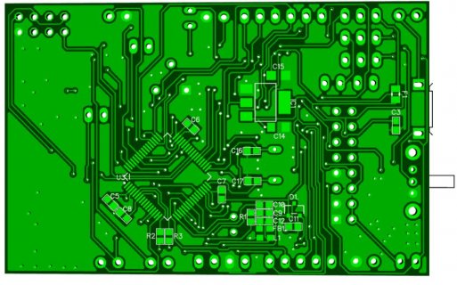
Hi I have developed the custom teensy 3.2 with my required extra module and its not getting flashed even with specific bootloader.
while burning what i saw is the programming windows just comes and goes like a flash.
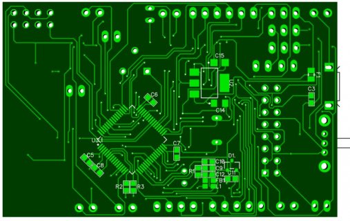
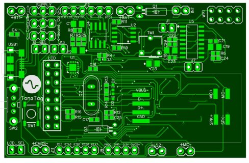
Kindly find the PCB images in attachment.
U1 is bootloader.
U3 is MK20DX256VLH7.
Q2 is 16Mhz.
R2 and R3 are 33 ohm.
kindly let me know the placement and position of above components are correct or not.
Also find the video of flashing and verbose log in attachment.
Verbose log
12:39:38 IST: Teensy Loader 1.25, begin program
12:39:39 IST: File "Blink.cpp.hex". 12288 bytes, 5% used
12:39:39 IST: Listening for remote control on port 3149
12:39:39 IST: initialized, showing main window
12:39:39 IST: remote connection opened
12:39:39 IST: remote cmd: "comment: Teensyduino 1.25 - LINUX64"
12:39:39 IST: remote cmd: "dir:/tmp/build106311147377904526.tmp/"
12:39:39 IST: remote cmd: "file:Blink.cpp.hex"
12:39:39 IST: File "Blink.cpp.hex". 12288 bytes, 5% used
12:39:39 IST: remote cmd: "status"
12:39:39 IST: status data sent
12:39:39 IST: remote cmd: "auto n"
n"
12:39:39 IST: remote connection closed
12:39:39 IST: HID/linux: bus "001", device "002" vid=8087, pid=8000, ver=0004
12:39:39 IST: remote connection opened
12:39:39 IST: remote cmd: "status"
12:39:39 IST: status data sent
12:39:39 IST: remote cmd: "status"
12:39:39 IST: status data sent
12:39:39 IST: remote cmd: "status"
12:39:39 IST: status data sent
12:39:39 IST: remote cmd: "status"
12:39:39 IST: status data sent
12:39:39 IST: remote cmd: "status"
12:39:39 IST: status data sent
12:39:39 IST: remote cmd: "status"
12:39:39 IST: status data sent
12:39:40 IST: remote cmd: "status"
12:39:40 IST: status data sent
12:39:40 IST: remote cmd: "status"
12:39:40 IST: status data sent
12:39:40 IST: remote cmd: "status"
12:39:40 IST: status data sent
12:39:40 IST: remote cmd: "status"
12:39:40 IST: status data sent
12:39:40 IST: remote cmd: "status"
12:39:40 IST: status data sent
12:39:40 IST: remote cmd: "status"
12:39:40 IST: status data sent
12:39:40 IST: remote cmd: "status"
12:39:40 IST: status data sent
12:39:40 IST: remote cmd: "status"
12:39:40 IST: status data sent
12:39:40 IST: remote cmd: "status"
12:39:40 IST: status data sent
12:39:40 IST: remote cmd: "status"
12:39:40 IST: status data sent
12:39:41 IST: remote cmd: "status"
12:39:41 IST: status data sent
12:39:41 IST: remote cmd: "status"
12:39:41 IST: status data sent
12:39:41 IST: remote cmd: "status"
12:39:41 IST: status data sent
12:39:41 IST: remote cmd: "status"
12:39:41 IST: status data sent
12:39:41 IST: remote cmd: "status"
12:39:41 IST: status data sent
12:39:41 IST: remote cmd: "status"
12:39:41 IST: status data sent
12:39:41 IST: remote cmd: "status"
12:39:41 IST: status data sent
12:39:41 IST: remote cmd: "status"
12:39:41 IST: status data sent
12:39:41 IST: remote cmd: "status"
12:39:41 IST: status data sent
12:39:41 IST: remote cmd: "status"
12:39:41 IST: status data sent
12:39:42 IST: remote cmd: "status"
12:39:42 IST: status data sent
12:39:42 IST: remote cmd: "status"
12:39:42 IST: status data sent
12:39:42 IST: remote cmd: "status"
12:39:42 IST: status data sent
12:39:42 IST: remote cmd: "status"
12:39:42 IST: status data sent
12:39:42 IST: remote cmd: "status"
12:39:42 IST: status data sent
12:39:42 IST: remote cmd: "status"
12:39:42 IST: status data sent
12:39:42 IST: remote cmd: "status"
12:39:42 IST: status data sent
12:39:42 IST: remote cmd: "status"
12:39:42 IST: status data sent
12:39:42 IST: remote cmd: "status"
12:39:42 IST: status data sent
12:39:42 IST: Verbose Info event
12:39:43 IST: remote cmd: "status"
12:39:43 IST: status data sent
12:39:43 IST: remote cmd: "status"
12:39:43 IST: status data sent
12:39:43 IST: remote cmd: "status"
12:39:43 IST: status data sent
12:39:43 IST: remote cmd: "status"
12:39:43 IST: status data sent
12:39:43 IST: remote cmd: "status"
12:39:43 IST: status data sent
12:39:43 IST: remote cmd: "status"
12:39:43 IST: status data sent
12:39:43 IST: remote cmd: "status"
12:39:43 IST: status data sent
12:39:43 IST: remote cmd: "status"
12:39:43 IST: status data sent
12:39:43 IST: remote cmd: "status"
12:39:43 IST: status data sent
12:39:43 IST: remote cmd: "status"
12:39:43 IST: status data sent
12:39:44 IST: remote cmd: "status"
12:39:44 IST: status data sent
12:39:44 IST: remote cmd: "status"
12:39:44 IST: status data sent
12:39:44 IST: remote cmd: "status"
12:39:44 IST: status data sent
12:39:44 IST: remote cmd: "status"
12:39:44 IST: status data sent
12:39:44 IST: remote cmd: "status"
12:39:44 IST: status data sent
12:39:44 IST: remote cmd: "status"
12:39:44 IST: status data sent
12:39:44 IST: remote connection closed
while burning what i saw is the programming windows just comes and goes like a flash.
Kindly find the PCB images in attachment.
U1 is bootloader.
U3 is MK20DX256VLH7.
Q2 is 16Mhz.
R2 and R3 are 33 ohm.
kindly let me know the placement and position of above components are correct or not.
Also find the video of flashing and verbose log in attachment.


Verbose log
12:39:38 IST: Teensy Loader 1.25, begin program
12:39:39 IST: File "Blink.cpp.hex". 12288 bytes, 5% used
12:39:39 IST: Listening for remote control on port 3149
12:39:39 IST: initialized, showing main window
12:39:39 IST: remote connection opened
12:39:39 IST: remote cmd: "comment: Teensyduino 1.25 - LINUX64"
12:39:39 IST: remote cmd: "dir:/tmp/build106311147377904526.tmp/"
12:39:39 IST: remote cmd: "file:Blink.cpp.hex"
12:39:39 IST: File "Blink.cpp.hex". 12288 bytes, 5% used
12:39:39 IST: remote cmd: "status"
12:39:39 IST: status data sent
12:39:39 IST: remote cmd: "auto
12:39:39 IST: remote connection closed
12:39:39 IST: HID/linux: bus "001", device "002" vid=8087, pid=8000, ver=0004
12:39:39 IST: remote connection opened
12:39:39 IST: remote cmd: "status"
12:39:39 IST: status data sent
12:39:39 IST: remote cmd: "status"
12:39:39 IST: status data sent
12:39:39 IST: remote cmd: "status"
12:39:39 IST: status data sent
12:39:39 IST: remote cmd: "status"
12:39:39 IST: status data sent
12:39:39 IST: remote cmd: "status"
12:39:39 IST: status data sent
12:39:39 IST: remote cmd: "status"
12:39:39 IST: status data sent
12:39:40 IST: remote cmd: "status"
12:39:40 IST: status data sent
12:39:40 IST: remote cmd: "status"
12:39:40 IST: status data sent
12:39:40 IST: remote cmd: "status"
12:39:40 IST: status data sent
12:39:40 IST: remote cmd: "status"
12:39:40 IST: status data sent
12:39:40 IST: remote cmd: "status"
12:39:40 IST: status data sent
12:39:40 IST: remote cmd: "status"
12:39:40 IST: status data sent
12:39:40 IST: remote cmd: "status"
12:39:40 IST: status data sent
12:39:40 IST: remote cmd: "status"
12:39:40 IST: status data sent
12:39:40 IST: remote cmd: "status"
12:39:40 IST: status data sent
12:39:40 IST: remote cmd: "status"
12:39:40 IST: status data sent
12:39:41 IST: remote cmd: "status"
12:39:41 IST: status data sent
12:39:41 IST: remote cmd: "status"
12:39:41 IST: status data sent
12:39:41 IST: remote cmd: "status"
12:39:41 IST: status data sent
12:39:41 IST: remote cmd: "status"
12:39:41 IST: status data sent
12:39:41 IST: remote cmd: "status"
12:39:41 IST: status data sent
12:39:41 IST: remote cmd: "status"
12:39:41 IST: status data sent
12:39:41 IST: remote cmd: "status"
12:39:41 IST: status data sent
12:39:41 IST: remote cmd: "status"
12:39:41 IST: status data sent
12:39:41 IST: remote cmd: "status"
12:39:41 IST: status data sent
12:39:41 IST: remote cmd: "status"
12:39:41 IST: status data sent
12:39:42 IST: remote cmd: "status"
12:39:42 IST: status data sent
12:39:42 IST: remote cmd: "status"
12:39:42 IST: status data sent
12:39:42 IST: remote cmd: "status"
12:39:42 IST: status data sent
12:39:42 IST: remote cmd: "status"
12:39:42 IST: status data sent
12:39:42 IST: remote cmd: "status"
12:39:42 IST: status data sent
12:39:42 IST: remote cmd: "status"
12:39:42 IST: status data sent
12:39:42 IST: remote cmd: "status"
12:39:42 IST: status data sent
12:39:42 IST: remote cmd: "status"
12:39:42 IST: status data sent
12:39:42 IST: remote cmd: "status"
12:39:42 IST: status data sent
12:39:42 IST: Verbose Info event
12:39:43 IST: remote cmd: "status"
12:39:43 IST: status data sent
12:39:43 IST: remote cmd: "status"
12:39:43 IST: status data sent
12:39:43 IST: remote cmd: "status"
12:39:43 IST: status data sent
12:39:43 IST: remote cmd: "status"
12:39:43 IST: status data sent
12:39:43 IST: remote cmd: "status"
12:39:43 IST: status data sent
12:39:43 IST: remote cmd: "status"
12:39:43 IST: status data sent
12:39:43 IST: remote cmd: "status"
12:39:43 IST: status data sent
12:39:43 IST: remote cmd: "status"
12:39:43 IST: status data sent
12:39:43 IST: remote cmd: "status"
12:39:43 IST: status data sent
12:39:43 IST: remote cmd: "status"
12:39:43 IST: status data sent
12:39:44 IST: remote cmd: "status"
12:39:44 IST: status data sent
12:39:44 IST: remote cmd: "status"
12:39:44 IST: status data sent
12:39:44 IST: remote cmd: "status"
12:39:44 IST: status data sent
12:39:44 IST: remote cmd: "status"
12:39:44 IST: status data sent
12:39:44 IST: remote cmd: "status"
12:39:44 IST: status data sent
12:39:44 IST: remote cmd: "status"
12:39:44 IST: status data sent
12:39:44 IST: remote connection closed


