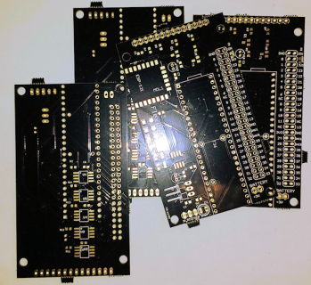
T3.x Flexiboard(?)

Status
Not open for further replies.

Frank B

Senior Member
Edit:
Link to board @ PCBs.io: https://pcbs.io/search?query=flexiboard
Costs: $24.53 for a set of 4

https://github.com/FrankBoesing/FlexiBoard

More information in Post #22

Hi,

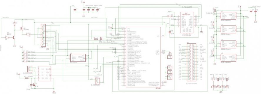
I'd like to make a new Board. It would be great if you can check the schematic if there are any problems :)

It will be soldered to the ILi9341 Touch-Display and I tried to choose the pins in a way that all components are optional and it works with all Teensy 3.x (T3.0 .. T3.1 without Esp8266)

- PWM for Display-Backlight
- WLAN with ESP8266 (Board ESP12e), Hardware-Handshake with RTS and CTS possible, Flashing the ESP is possible, i hope EDIT: IS possible)
- Audio either DAC0/DAC1, PT8211, or Audioshield (without PIN 15, volume-pot)
- if no Audioshield, there are Pads to solder a W25Q128 Flash
- connector for IR-Recieve (for example TSOP xyz Chips, or Sharp, or...)
- connector for IR-Transmit

Edit:
- added 4 more JEDEC - Memory (Flash or RAM) (T3.5 / 3.6 only)
- added 4 LEDs (T3.5 / 3.6 only)
- added pinheader for VBAT (all T3.x)

Pictures: See post #9

Attention: SPI0 is not connected to the big pinheader!

All is optional, even the display..


All hints welcome :)

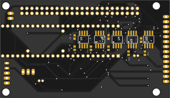
Edit: some pics:
2016-10-01 16.12.59k.png2016-09-30 20.37.22k.jpg2016-09-30 20.38.55k.jpg
 
Last edited:
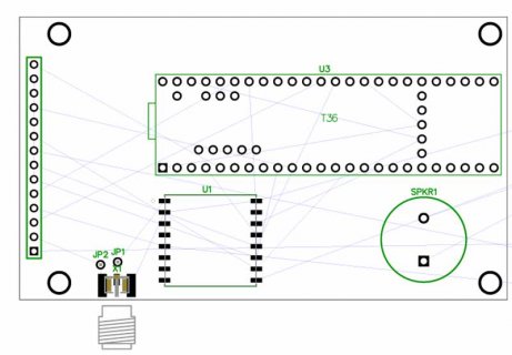
I've added a kind of "Memoryboard" on the backside, with 6x RAM (23LC1024) or Flash with CS-Signals on Pins 28,29,30,31,32,35

flexboard_brd2.png
 
Last edited:
When can I order one :) I ordered six KS T_3.6's and at least one should be on a board like this Good work Frank, thanks for sharing!

I have used Teensy to Program the ESP many times (with your proxy code Frank) over Serial1 and it works! Also even better the ESP can have a sketch that allows OTA updates to the ESP! I have posts with links to Github that mentions my steps and move to a new SERVER library I found that incorporated OTA and more very cleanly - including setting the TIME from the WEB and serving WEB pages and allowing OTA updates of the ESP SPIFFS 'disk' file space to hold data or web pages! With life and PJRC beta work I have not looked at this in months.

<edit>: This post links to where I was on ESP8266 and Teensy: A-Guide-To-Using-ESP8266-With-TEENSY-3
 
Last edited:
Hi Frank, look great.

Might even order some if available.

For my Well monitoring system stuff, which maybe I will get back to soon after KS and beta stuff slows down, I want to do a board like this, but instead of Esp8266, use one of the LoRa modules...
 
It is odd not hitting the KS page each day to see where the counts. Maybe that is where I found time to do the EEPROM write code for T_3.6.

A takeoff for the LORA radios would be cool too - Frank it is an SPI device this thread shows pins : Using-SparkFun-s-RFM69HCW-and-Bi-Directional-Logic-Level-Converter-with-Teensy-3-2

The ESP has a lot more utility as a fully capable WiFi second 80 Mhz processor that runs Arduino and has onboard SPIFFS/FLASH/disk space. But not the long range radio feature of the LORA.

Just looked at the p#2 drawing - with the memory on the bottom there isn't room to castellate and bring out any bottom pins - not that you needed them
 
Frank,
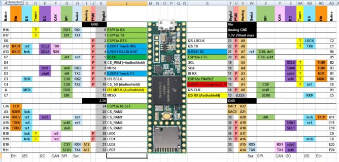
Really like your use of the spreadsheet for the pin numbering. I'm definitely going to have to do that. Are columns L and S for signal names on this project?

I'm thinking of adding a Project title, date and version number up at the top. I could then stick that number onto the various breadboards I have all over the place to keep track of whats what.

On your Flexiboard, whats the blue-ish area next to the ESP for?

Just for the heck of it maybe try to keep traces (and parts?)away from under the ends of the Teensy 3.x where you might be prying one off.
 
If you made room for any castellated area:: pull out the T_3.5/3.6 Debug pins? Nothing would be worse than building this stack and having something fail and not having the opportunity to work it out when the debugger support gets here.

Of course plan a way to get to T_3.6 2nd USB pins.

{ BTW: I told myself not to feature creep this for you . . . looks like that lasted 2 hours :) ... if you ignore the LORA comment prompted by Kurt }
 
@bicycleguy, the spreadsheet is (c) by BEN: https://forum.pjrc.com/threads/34808-K66-Beta-Test?p=114619&viewfull=1#post114619
@Kurt, I'll upload the EAGLE-Files to github when I know that the board is OK.
@Tim, i'll save the castellated area and other components for Rev 2 :)

I reduced the number of Mem-chips to 4 + the extra one (=5), and removed SPI0 from the big connector. I want that the display works with 70Mhz, and the connections need to be short.
But i added 4 LEDs

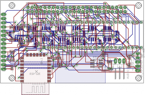
This is the final version (I hope it works..) :

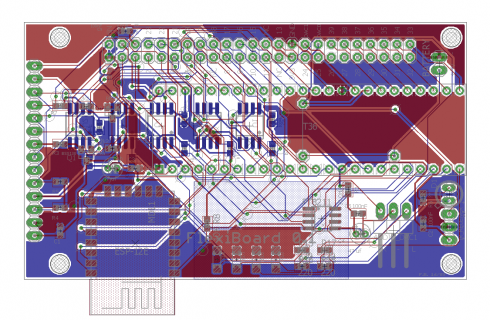
schematic.jpgboard.pngspreadsheet.jpg
Top:
top.svg.m.png
Bottom:
bottom.svg.m.png

It matches exactly the size of the ILI9341-touch display.

I've updated post #1 with the new specifications
 
Last edited:
Hi, interesting thread
for what you are thought to this board?
which use?

Different projects.. Its a general purpose board for me. Often, my projectes involve the display and / or sound, wlan, or extra memory.
I found the first problem.. the position of the teensy 3.2 pins for vbat and dac are wrong :(. Ok, not a big problem.
 
I hope it works too :)

If I'm looking right - I see now the display goes under the PCB (as pictured) and the Teensy on the up side with the ESP. So a custom designed debug board could bring those pins out for use - if carefully installed in the right configuration
 
Hi Frank,

As I mentioned earlier your board looks interesting and very well may build one.

I have been thinking along that line for well monitoring system, which I want to get back to. As I mentioned for this setup I am thinking about using LoRa modules and have purchased a few of them from Adafruit, but I am also thinking of instead for these boards connecting the RFMxxx chips directly to the main board as the main thing Adafruit adds is voltage translations... Sorry I don't want to hijack your thread, but some of my mental questions to my self also relate to your board.

I have not done much to layout the board yet, as waiting to see how yours turns out, plus trying to decide what I want on the board.

Some of the questions I have for both setups include:

a) How are you powering this board? Through USB or I see a 3v battery connection. Are you assuming external Voltage Regulator? Sorry may be on schematic, but can not really read it... Although on closer inspection I think the battery is for the VBat?

a1) If I wish for the board to have a 3.3v VR on it, can I power the Teensy and the LED display from it, or do I need 5V (3.6-6V)?

b) How to put into case. If I print a 3d box to hold this, how to get to everything, in particular SDCard and USB. Probably USB extension cable with case mount on other side... Maybe a good product for PJRC to carry.

c) Sound: In your case I believe you are setting it up mainly for remote powered speakers? In my case I may want internal speaker may not need as much sound quality, probably something closer to using Prop Shield. Have not checked your setup to see if compatible with it?

Again sorry I don't wish to hijack. I started playing around to get an idea of sizes. and have not gotten far yet...

DipTrace-PCB---Teensy-3.jpg

Again only shows layout of connector for display, plus T3.6, plus. RFM95 or like and the speaker I used in previous board, to get an idea for size. Will probably move ANT to a side... Or maybe wait until yours comes out and then try building one and see how far the Wifi extends...
 
Last edited:
Hi Kurt,
no problem this thread is not "hijackable" :) I'm very interested in alternate ideas.

My goal is to have one board for different projects, a "one fits all" or "one fits many" - this board is ok for 99% of my projects, i think. If not - well, there is still the 48 pin-connector for extensions. And if I don't want a feature, there's no need to solder its components. Easy.

Power: I decided to take the most easy route and use the USb-Connector only. This way, i don't have to cut the trace on the bottom of the teensy and can swap it with an other teensy. I'll use a female USB-Connector and a short USB-Cable later - If i want to use Battery ("Powerbank?") or other source.
VBAT is for RTC only, yes. I use a two pins connector for batteries like this : https://www.amazon.de/Batterie-Batt...g_3?ie=UTF8&psc=1&refRID=V9ZN2NQN4ZDVGW68V82R
Edit: The connector on the picture does not fit (the one my board is larger), but you get the idea :)

a1) Hm.. not sure. But is easy to test/try..

b) very good question !!!! I'm still searching ! let me know if you find something..

c) Yes, it's for remote speakers. But there are very cheap little amps on breadboards (china..:) ) which can be used. They are so small that they can be mounted on the speaker..

For example something like this:

attachment.php

(You can buy them without volume-pot, too.. picture taken from the PT8211 thread)
 
Last edited:
Thanks Frank,

I totally understand keep it simple (Not that typically ever achieve it)

So depending on size constraints I can see several options. Punt, or Add connector for external battery, plus jumpers to choose either USB or exterior... Another option would be to set it up to be able to run with something like Pesky Products Lipo charger, although at least by pictures typically mounted under Teensy.

The other question I have to checkout is if I use the RFM9x radio, does the Teensy provide enough 3.3v for it, or should I add it's own regulator...

As for VBat, I have not actually ever used it, but might for some of this potential stuff.. Not sure, might setup to use something like you mentioned, which looks similar to the batteries sold for Odroids and others. Or could setup to use one of the surface mount coin battery holders that spark fun sells. Maybe mount it on the same side as the display, where it sort of aligns with the SD Card holder. Might need to print some spacers to go between the display and the board, but probably will anyway.

USB connectors not sure which one yet, I used one earlier on a Remote control. I do see some out there like: Maybe something like: https://www.adafruit.com/products/937

Sound, might have to try something like you mentioned. On another board, I set it up to hopefully use a simple setup like propshield. It has on it a LM4862 chip and is one of these speakers: http://www.digikey.com/product-search/en?keywords=CVS-1508

Have not built it yet, so don't know how well it will work.

Edit: The other thing I wonder in my case, should I leave everything on SPI0? Or should I maybe move the RFM9x to maybe use SPI1 (or 2)

Thanks again
 
Last edited:
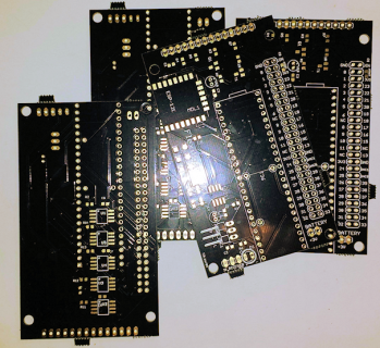
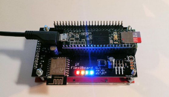
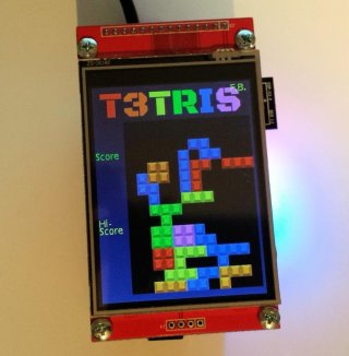
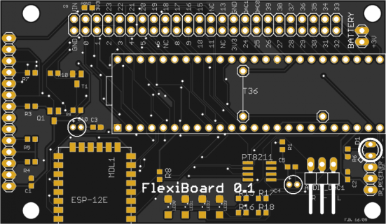
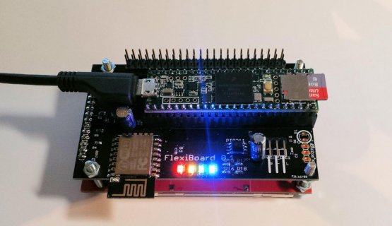
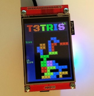
Got my FlexiBoard today, and could'nt resist to solder it and make a few tests:

2016-09-30 20.37.22k.jpg
2016-09-30 20.38.55k.jpg

So far, all seems to work, but i hav'nt tested SPI FLASH/RAM, WLAN and IR Send+Recv.
 
Since it is not cheap to produce them:
I would like to gift a board to a student. Preferably from Germany, age < 25.
Please: Answer only if you really want to use it :) Thanks.

2016-10-01 16.12.59k.png


I'll add an ESP8266 (ESP-12) and the I2S-Chip (PT8211).
No costs.
 
Last edited:
I would love to test it! I'm an aerospace student from Berlin, currently making my masters degree. Hopefully my teensy 3.6 and 3.5 will arrive soon, then I could use it to test these new boards, and post my thoughts and progress here
 
Hi,

kein Thema, schick mir deine Adresse per PM ! Du brauchst nichts großartig zu testen, benutze es einfach - es ist ein Geschenk - ich habe 5 davon bekommen, und mit so vielen kann ich nichts anfangen. Würde mich natürlich freuen wenn Du damit etwas baust und ein Foto postest, oder Ideen für eine Version 0.2 hast. :)

Ich habe keine Verkaufspläne oder ähnliches - ist nur ein Hobby.

Frank
 
Link to board @ PCBs.io: https://pcbs.io/search?query=flexiboard
Costs: $24.53 for a set of 4

Github: https://github.com/FrankBoesing/FlexiBoard

All but 4x SPI memory tested (will do that tomorrow). Flash on U1 works.

Errata:
- Wrong location for Teensy 3.1/3.2 VBAT/DAC0 Pins (still possible to use them with a bit fiddling.. or use Teesy 3.5/3.6)
- Due to an error, pins 24-32 are not routed to the 48-Pin-connector :-( FIX: Patch them on the backside.
- Limited IR-Send power, but works for distances ~2m. For more power, add a (extern) transistor.
- The connector for the IR-Receiver is + - OUT, but most IR -Receivers use - + OUT Fix: Do not mount directly and use a cable

Needed Parts:
Code:
Partlist

Part        Value              Device                    Package


Mount all:
C1          100nF              C-EUC0603                 C0603
C2          100nF              C-EUC0603                 C0603
C3          100nF              C-EUC0603                 C0603
C5          100nF              C-EUC0603                 C0603
C6          100nF              C-EUC0603                 C0603
C7          100nF              C-EUC0603                 C0603
C8          100nF              C-EUC0603                 C0603
C9          100nF              C-EUC0603                 C0603

[I]JP1                            PINHD-2X24                2X24[/I]

WLAN
=====
ESP8266-ESP12E
C10         100 uf             CPOL-EUE1.8-4             E1,8-4
R8          10K                R-EU_R0603                R0603

AUDIO
=======
PT8211      PT8211SO8          PT8211SO8                 SO8
AUDIO_DAC1                     PINHD-1X3/90              1X03/90
C4          47 uf              CPOL-EUE1.8-4             E1,8-4
R1          10 Ohm             R-EU_R0603                R0603

MEMORY
======
For example RAM 23LC1024 or Flash W25Q128

U1          JEDEC-Memory                        SOIC-8
U2          JEDEC-Memory
U3          JEDEC-Memory
U4          JEDEC-Memory
U5          JEDEC-Memory
R2          10k                R-EU_R0603                R0603
R11         10k                R-EU_R0603                R0603
R12         10k                R-EU_R0603                R0603
R13         10k                R-EU_R0603                R0603
R14         10k                R-EU_R0603                R0603


IR RECEIVE
==========
For example TSOP1136 or many others.
IR_RECEIVER TSOP..             PINHD-1X3                 1X03

IR SEND
==========
D1          IR Emitting Diode  ????                      ????
R6          100                R-EU_R0603                R0603

VBAT:
=====
VBAT                           PINHD-1X1                 1X01
VBAT1                          PINHD-1X1                 1X01
BATTERY                        PINHD-1X2                 1X02

LED:
======

LED0                           LEDSML1206                SML1206
LED1                           LEDSML1206                SML1206
LED2                           LEDSML1206                SML1206
LED3                           LEDSML1206                SML1206
R15         330 Ohm            R-EU_R0603                R0603
R16         330 Ohm            R-EU_R0603                R0603
R17         330 Ohm            R-EU_R0603                R0603
R18         330 Ohm            R-EU_R0603                R0603


DISPLAY
=======
ILI9341 with touch

T1          BC850              BC850                     SOT23
Q1          BSS138             BSS123                    SOT23
R3          10 Ohm             R-EU_R0603                R0603
R4          10k                R-EU_R0603                R0603
R5          10k                R-EU_R0603                R0603
R7          10k                R-EU_R0603                R0603
R9          1k                 R-EU_R0603                R0603
R10         1k                 R-EU_R0603                R0603
DISPLAY                        PINHD-1X14                1X14

Code:
Some useful #defines:
Code:
#define SCK  14
#define MISO 12
#define MOSI  7

#define LEDT 13   //Teensy-LED
#define LED0 29   //red
#define LED1 30   //orange
#define LED2 31   //green
#define LED3 32   //blue

const uint8_t ledArr[4] = { LED0, LED1, LED2, LED3 };
#define SETLED(_led,_onoff) {digitalWriteFast(ledArr[_led],_onoff);}

#define TFT_BACKLIGHT   4
#define TFT_TOUCH_CS    8
#define TFT_TOUCH_INT   3
#define TFT_DC          21
#define TFT_CS          15
#define TFT_RST         255  // 255 = unused, connected to 3.3V
#define TFT_SCLK        SCK
#define TFT_MOSI        MOSI
#define TFT_MISO        MISO

#define MEM0_CS         6
#define MEM1_CS         25
#define MEM2_CS         26
#define MEM3_CS         27
#define MEM4_CS         28

#define IR_RCV          17
#define IR_SND          5  //Shared with WLAN_GPIO0 !

#define WLAN_SERIAL     Serial1
#define WLAN_SERIAL_BAUD_INIT 74880
#define WLAN_SERIAL_BAUD 115200
#define WLAN_RESET      24
#define WLAN_ENABLE     16  //CH_PD
#define WLAN_CTS        20  //GPIO15
#define WLAN_RTS        2   //GPIO13
#define WLAN_GPIO0      5   //Shared with IR_SND !
#define WLAN_GPIO13     WLAN_RTS
#define WLAN_GPIO15     WLAN_CTS

void setBacklight(float brightness) { // ( range from 0 to 1.0 ) 
  int b;
  
  b = 256 - roundf(256.0f * brightness);
  
  if (b < 0) b = 0;
  if (b > 256) b = 256;
  
  analogWrite(TFT_BACKLIGHT, b); //(0=Max, 256=MIN)
}
 
Last edited:
Frank - do you have a T_3.5 pinned the same way you could try it with? IIRC - You once noted you tried a T_3.5 and it didn't work as expected? I ask because I had a display wired to headers and it failed on T_3.5 when the same header board on the T_3.6 worked. I just found my PJRC Purple OSH ILI9341 board that fits mine and the T_3.6 powered and worked - then on the T_3.5 at 120 the display drew but no touch worked? [reminds me I should go solder the T_3.5 header pins as that was done on the road and may not be good.]
 
Hopefully this is responsive to post #25? It seems this is just spam? But here is a note on what I did so far::

post #17 shows display on top when Teensy is on the bottom, though you can install display rotated out 180° so it gets really long but the display faces up with the Teensy on top. I had to do that as my beta Teensys have top headers so I have pins down from the PCB and the Teensy ends up under with the display rotated out.

Debugging pin usage is still an unknown but socketed like in p#17 the under pads for DEBUG could be wired and brought out - those under pads are not connected to the main PCB.
 
Last edited:
Status
Not open for further replies.
Back
Top