Teensy 3.2 Through-hole damaged due to bad soldering

Status
Not open for further replies.

surajjorwekar

New member
Hello, Bad day it was. Teensy not working due to bad soldering experiences.
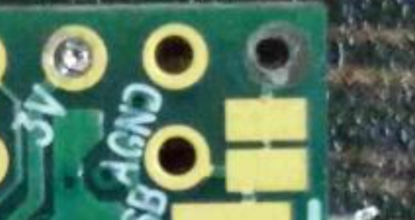
I soldered through holes near USB ie.e GND and Vin but wen i desoldered them the metal inside the through hole came out accidentally.
Anyone can please help me out ? Only 2 holes are damaged.
 
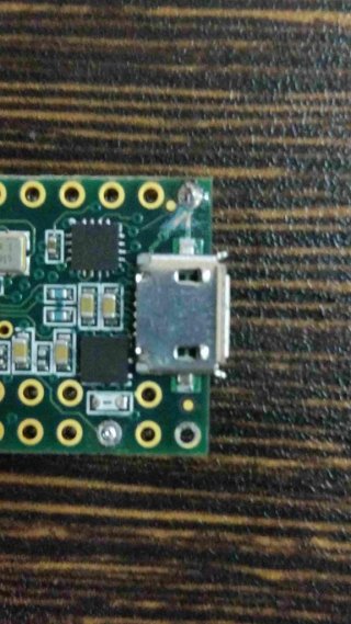
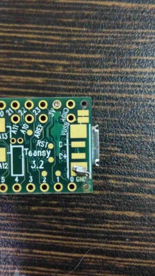
Can you post pics? If it is AGND you might live without that. Not sure if Vin hits the nearby pad there before or after the pin hole you lost - if the under pad (or internal VUSB hole) still gets Vin you might solder to that if you need power on that pin and USB still powers the board?
 
front teensy.jpgback.jpg
I donno if i made it more worse by again soldering. :(
 
It must have gotten very hot to take out that through hole metal? I've de-soldered some and not had a problem. If it got that hot it may have done other damage?

I don't know how the traces run to get power from the USB connector to the rest of the system. it seems the power might start on the under pads and run out to the VIN pinhole to feed the rest of the system.

If so it sounds like you have effectively made the "VIN from VUSB" cut indicated on the back of the card - only not as intended but beyond that pad nearest the pin where the power feeds the rest of the Teensy. Check for continuity between that outer pad and the VIN pin - on highest Ohm setting the reading should show 0, if no continuity - not ZERO - then it seems that is the case. The missing metal core from that VIN pin may have connected the layers internally - if so a good solder fill around the pin may fix it otherwise without that you'd have to do some fancy soldering elsewhere to take VIN from that pin to where it hits the regulator - perhaps in incoming side of the FUSE? Or just make sure that trace is cut and power from a true 3.3V supply on a 3.3V pin?
 
Last edited:
For future reference, what kind of soldering iron are you using? That looks like it was made with a very hot iron, either that or your technique may require some work - shouldn't need to apply heat to a pad for more that a couple of seconds.
 
Hoping someone else can confirm - the power connects internal to that pin hole?

This is just a casual observation - but you need to get this gap to VIN pin bridged back to the pin hole - I don't see another way to get power from that pad which would seem to explain what you are seeing:

t32connect.PNG
 
Even someone like me with over 30 years of experience can have mixed results with a cheap junk iron.
Get a proper temperature controlled iron.
You should never have to solder on a board above 250C and for no longer than 10 seconds.
As a general rule, if a board is made properly, and has proper thermal reliefs, you should never need anything above this temperature.
Only in rare cases, where either the tip is too thin, or the iron wattage is too low should you ever use a higher temperature with great care.
Don't use the tip like a chisel or dig into the board. use light pressure.
There are lots of videos on how to solder properly on YouTube, go watch them.
 
Hmm, I need 350C (proper temp controller iron) to get decent-ish results.
The solder barely melts at 250C. I'm using lead free solder, maybe that's it?

No, I too use lead-free, but what I am using is 99%SN. 250C is enough to do the melting with a large enough tip.
You may need to calibrate your iron.
Depending on the board, though, I'm usually OK up to 300C. I never exceed this temp unless I am soldering to a large back plane.
Point is, always start at a low temp, and raise it as needed.
Always having flux helps a lot too.

One thing that I find that people do when they just start out is they use too much heat and lack patience.
They do not wait before the joint is heated well enough before desoldering and rip out a thru-hole, and/or push really hard on the iron.
Either of these actions will delaminate a board and/or pull thru-holes right out.
Yes you can repair it, but it takes uber skillz. :rolleyes:
.
 
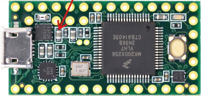
Yes, VIN uses that pad. If you've lost the metal inside the pad, your last chance to power the board from 5V is this:

teensy32mod.jpg

If you can make a connection to that side of the 2.2 uF capacitor, you can access the VIN net to apply power. But that will require delicate soldering work. Maybe get a better iron and some lead-based solder before trying such delicate work?
 
Yeah - that would be delicate or the cap will pop right off. A 30 gauge wire (wire wrap wire) should be big enough correct? And easier to solder with less heat.

I'm new at reading schematics: The Fuse is on the other side of the VIN pin and won't be in the system then?
 
Status
Not open for further replies.
Back
Top