teensy 3.2 pin mux control

Status
Not open for further replies.

twilkers

Well-known member
I'm having trouble with A4-7 as analog inputs, suspect I might have a pin muxing problem. That is, the defaults are not working for me. So, plowing through the K20 sub family manual.

I found the default mux state in table in section 10.3.1.

However, what I don't see is the specific syntax for the code to change registers.

can someone point me to this? An example would be stellar!

thanks,
tim
 
Last edited:
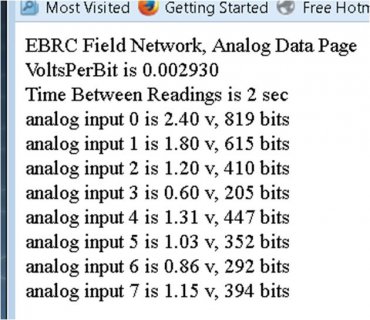
here is the code and a webpage example.

ch4-7 should be 2.0, 1.5, 1.0, 1.8v from a resistive divider. A0-3 are correct.
 

Attachments

  • teensy_webserver_RevC.ino
    11.6 KB · Views: 93
  • voltages revC.jpg
    voltages revC.jpg
    60.1 KB · Views: 99
I found analog.c here which seems to control all the setup which is part of the puzzle.

C:\Program Files (x86)\Arduino\hardware\teensy\avr\cores\teensy3

I can control resolution using adcReadRes();

but still cannot get accurate readings on A4-7.

what am I doing wrong?
 

Attachments

  • voltages revD 12bit.pdf
    476.2 KB · Views: 117
the v/bit is the correct number and a #define. I'm using an external voltage reference of 3.0v.

I am measuring this voltage it on A7 but the measurement is clearly not correct although measures correct on the pin.
 
Double check the ground being used for reference. Other threads on the forum seem to have fixed their analog read problems by using the correct AGND reference.
 
IME, there is no difference between the ADC pins. They should work.

Have you tried a minimal sketch like this:
Code:
const uint8_t pin = A7;

void setup() {
    pinMode(pin, INPUT);
    Serial.begin(9600);
    delay(2000);
}

void loop() {
    Serial.println(analogRead(pin));
    delay(1000);
}

Have you tried swapping pins / channels around?

What's the output resistance of your voltage dividers? At 10kOhm or so the Teensy ADC accuracy starts going downhill.
 
I use two strings of 1k resistors, one for A0-3 and another for A4-7. 1k between each input and to gnd.

For the A0-3 string, there is 1k resistor to Vref(3.0v).
For the A4-7 string there is 2k between the string and Vref. Makes nice even numbers, 2.0, 1.5, 1.0v.

For A4-7 I have verified the voltages at the teensy pins with a multimeter to be as expected. For A7, there is an extra voltage divider to measure Vref, so the verified voltage at the pin is 1.2v.

I have a pretty minimalist sketch but using Ethernet. I could push the measurements to serial if that would help.
 
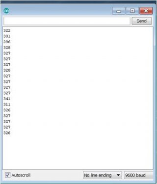
tni, I ran the minimalist sketch above, still off and stability issues. this translates to about 0.95v and pin has 1.2v on it.

do you have insight to possible mux issues? I had to cut A4 and A5 away from I2C traces on the sparkfun adapter, so it would not be surprising to me if the pin mux was setup for those digital lines and not analog inputs. It's not clear to me how to change how the pin is used by the sketch.
 

Attachments

  • voltages revE simple 10 bit.jpg
    voltages revE simple 10 bit.jpg
    15.7 KB · Views: 96
tni, I ran the minimalist sketch above, still off and stability issues. this translates to about 0.95v and pin has 1.2v on it.
That very strongly suggests that your hardware is screwed up.
do you have insight to possible mux issues?
That minimal sketch should set up everything properly. I don't know if the digital blocks are completely disconnected, but that should only make a very minor difference. If your hardware setup is ok, it should just work.
I had to cut A4 and A5 away from I2C traces on the sparkfun adapter,
Maybe you cut too much or created a short. Or maybe your analog shield isn't wired the way you think. Those readings you posted could be a floating input.
so it would not be surprising to me if the pin mux was setup for those digital lines and not analog inputs.
That should only make a very tiny difference.
It's not clear to me how to change how the pin is used by the sketch.
If you mean the one I posted, just change the "pin" at the top; A0 - A7 are the analog ones you are presumably using.

Anyway, I would take everything apart (assuming its not soldered) and connect some known voltage (ground and 3.3V are available on Teensy pins) to the Teensy analog pins to make sure your Teensy is working:
https://www.pjrc.com/teensy/pinout.html

My sketch will use the standard 3.3V power supply as reference voltage. A 3.3V reading would be 1023.
 
you are correct, I made a poor mod on the board.

BTW, my sketch is in post #3.

thanks for the second set of eyes!
 
Last edited:
I think my question is at a different level than your response.
Not really.
when I say "mux" I'm referring to how the MK20 chip muxes multiple functions on a single pin of the micro controller and requesting guidance on how to change that at the code level.
I'm telling you it doesn't make a difference as long the pin is configured as input like in my sketch. If you are not getting proper readings with my sketch, you have some fundamental problem with your hardware that you have to solve.

Throwing some complex pile of code that uses other libraries (which may do or may not do strange things) at the problem doesn't make troubleshooting easier. You have to be able to walk before you can run.
 
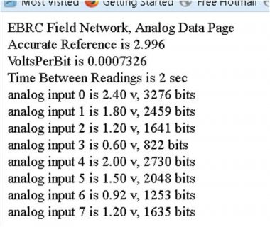
you are correct, I made a poor mod to my board. thanks for the second set of eyes
 

Attachments

  • voltages revF working.jpg
    voltages revF working.jpg
    43.9 KB · Views: 80
Last edited:
Status
Not open for further replies.
Back
Top