Connecting Teensy 3.2 to Prop shield for LED strip(APA102)

Status
Not open for further replies.

Tejkaran

Well-known member
Just wanting to know what connects where.
I have already soldered some pin headers to my Teensy which means that I am unable to connect it to the prop shield dieectly so I need to wire from Teensy to Prop shield.
I am using the prop shield to be used with LED strip(APA102)

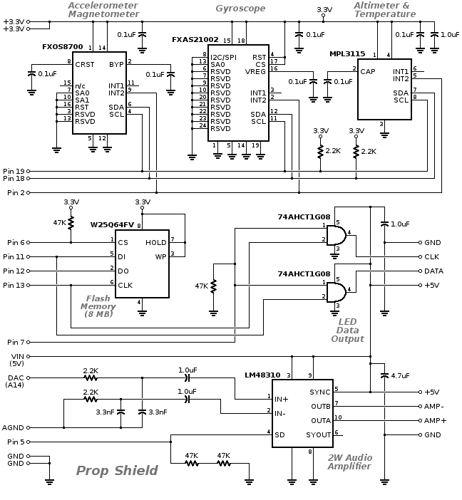
At one end you have (I presume this is the input for power end - call this end 1)
5V, -, +, GND

at the other end you have (I presume this is the output end - call this end 2)
GND, CLK, DATA, 5v

So do I connect GND and Vcc(5v) to end 1 pins labelled GND and 5V
5V to pin 7 to make it high
and then the data and clock wires for the LED strip to end 2 pins data and clock?

thanks in advance
 
If you look at the schematic on the Prop shield page: http://www.pjrc.com/store/prop_shield.html

You will see that you need to connect GND, +5v (VIN pin), probably 3.3v (not for the actual leds, but maybe to keep flash memory from being used.

Then you need to connect up pins 11 and 13, between the two, which are the SPI pins that are used by the LED and pin 7, which is the enable for the two pins.

You do have choices here. For example Pin 7, you can actually hook up to any IO pin or you can just tie it high (3.3v to be safe). Likewise pins 11 and 13 are default SPI pins. You could choose to connect these up to alternative pins that are alternates for SPI...

Good luck
 
To be honest, I don't really understand what you have said there on the whole.
I can see this schematic on the link you have said, but I don't see how that shows the links to the Teensy, because I am not all that great at reading schematics
7QUe5WG.png


I can see this image

So the 4 holes on the left (GND, Speaker-/+ & 5V) do they connect to anything?

If not, is it as such:
Prop --> Teensy
GND--> GND
Vin-->Vin
3.3v-->3.3V
11-->11
13-->13
Set pin 7 to high
Then you connect the APA102 to the 4 holes on the right hand side(Gnd,CLK,DAT,5v)

I understand what you say with pins 11&13, that you can use 7,11,13 or 14. But I will stick with 11&13 as i have always used them.
 
Others with more hardware experience here can probably answer better, but here are a few comments.

The 4 pins on the left are if you are using sound output capabilities of the prop shield.
The +5v/Gnd: are internally connected to the Vin/GND pins of the prop shield which you are already connecting. They can be used if your speaker needs power. When I have used the prop shield, I was using simple speaker which connected only to the Speaker +/- pins. But to use this, you need to connect additional pins for the sound system. In particular the DAC shown in above picture as AudioIN, also AGND (shown in picture AudioGND), and pin 5 as audio enable. Again this can be wired to pin or wired high...

As for the 4 pins on right for APA102s. Yes, you can hook all of them up to the light string. However depending on how many lights you are trying to use, you may not want to use the +5v here to drive your LEDS, but instead use an external power supply (or supplies) to power your lights. In this case you may not hook up the +5v here. You still need a common ground. Then you hook up your external power +5v to the +5v connector of the strip, plus again you need to connect up a ground connection between the two.
 
Got it working.
So need to power it up with GND and 5V Power
11 to 11 and 13 to 13
7 is set to high
and then data and clock to feed the led strip.
as you say, power for led strip does not need to come via the prop shield
no need to do anything to 3.3V

Thanks KurtE :)
 
In addition to the LEDS, if you want to use sound, you need to connect Audio GND, normal ground, the DAT pin, and 3.3v to their respective pins. You either need to connect 5 to 5, or just connect 5 to 3.3v to enable it.

If you also want to use flash memory, you need to connect 3.3v to 3.3v, normal ground to normal ground, 12 to 12, 6 to 6, and connect 7 to 7 (rather than just making 7 high, because you have to turn 6 on and 7 off to access memory and 7 on and 6 off to flash the LEDs). You will need 3.3v and normal ground.

If you also want to use the sensors on the motion sensor board, you need to connect the i2c pins A4 to A4 and A5 to A5, and probably connect 2 to 2 (2 is the i2c interrupt pin). You will need 3.3v and normal ground. You will not need pull-up resistors, because the prop board supplies 2.2K pull-up resistors on the i2c bus. The i2c addresses 0x1E (FXOS8700), 0x20 (FXAS21002), and 0x60 (MPL3115) are used by the motion sensors.
 
Last edited:
Status
Not open for further replies.
Back
Top