Teensy LC, Changing PinMode during runtime?

Status
Not open for further replies.

BambooSam

Active member
Can I change PinMode(Output/Input) in main loop? ... Safely?

I am working on a project where I would very much like to have to only use 1 digital pin as an Input and Output, not simultaneously of course. The pin only serves as a notification line, thats all. At some point one teensy will act as a receiver and sometimes a transmitter and the other teensy vise versa.
I will pay close attention to make sure that both wont ever be set as OUTPUTs at the same time.

In the event that both are set to OUTPUT and either one or both set HIGH, what can I do to not destroy those pins? Would a resistors in series help?

Thanks guys


EDITED:

To clarify:

At some point I will want Teensy1 (T1) to be listening to T2, it will be listening to see if T2 has set its pin to HIGH,
but other times I will want T2 to be listening to T1, listening to see if T1 sets its pin HIGH.
They should never be transmitting at the same time. (Pins set to OUTPUTS)
In the event that they do both set their pins to OUTPUTS and HIGH I need to make sure that I don't destroy those pins
 
Last edited:
I'm sure there will be better answers soon but one way I think would work is hook one end a single resistor say 100k to 3.3v then connect one one end of much lower value resistors say 10k to the other end of the 100k. The other end of each oh the 10k would go to one of the teensy's. When all the teensys are in input mode their pins will be high. When one pulls it low the voltage will drop to 0.3v. If one is high and one is low you will have 20k resistance between the outputs. I'm new to teensy and I haven't checked if the teensy output an be open collector but if it can be the 10k's wouldn't be needed.
 
I still have the breadboard setup at home, I'll try and capture it on the O-scope tonight.
 
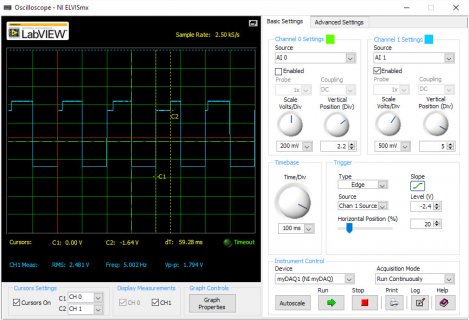
So I captured the transitions between PinModes

There's a glitch that occurs when transitioning from PINMODE(#,OUTPUT), DigitalWrite(#,LOW) to PinMode(##,INPUT).
The duration of the glitch is not constant, and varies from 0 to about 80ms.
Before you ask, it's also there with digitalWriteFast().
Paul alludes to this issue somewhat on his page about Using Digital I/O Pins in the section "Input With Pullup"

Here's a screen capture of the oscilloscope on pin(20), Running on a Teensy3.1:
O_Scope Capature.jpg

Code:
void setup() {}

void loop() { 

	pinMode(20, OUTPUT);
	  digitalWrite(20, LOW);
	  delay(100);
	  
	pinMode(20, INPUT);
	  delay(100); 
}

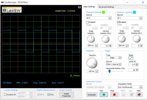
However the glitch goes away when using PinMode(#,INPUT_PULLUP).

Here's the O-Scope capture:
O_Scope Capture2.jpg

Code:
void setup() {}

void loop() { 

	pinMode(20, OUTPUT);
	  digitalWriteFast(20, LOW);
	  delay(100);
	  
	pinMode(20, INPUT_PULLUP);
	  delay(100); 
}

BTW, I'm finally getting a real scope. My wife is getting me a RIGOL DS1054Z for my birthday....Should I hack it??
 
Last edited:
Was going to ask and I see you meant ms not us based on the 100ms dwell time!

Just wondering what happens with this?
Code:
void loop() { 
	pinMode(20, OUTPUT);
	  digitalWriteFast(20, LOW);
	  delay(100);
	  
	pinMode(20, INPUT_PULLUP);
	pinMode(20, INPUT);
	  delay(100); 
}
 
Odd - my other thought was to put this :
pinMode(20, INPUT_PULLUP);
delay(1);
pinMode(20, INPUT);
delay(99);

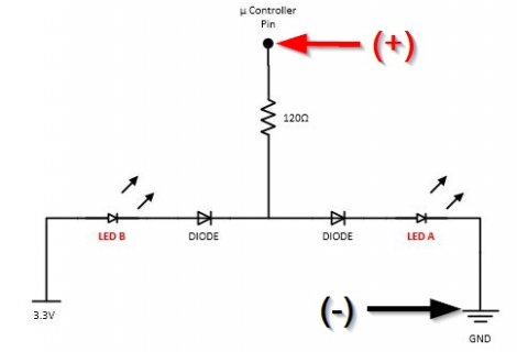
@tni - Wozzy linked it to his two LED's on one pin - not sure if that is the only way it was tried.
 
What is connected to the pin, while you are switching? Is it floating?

No, I'm measuring across the resistor and diodes in this circuit:
The arrows indicate probe locations
2016-10-08 13_24_21-Two LEDs from a Single Pin.jpg
It was in this post that I originally noticed the glitch while observing the LEDs
 
Last edited:
what happens if you just measure the voltage at the pin

manitou,
There. really nothing to measure in the transition from OUTPUT, LOW to INPUT or INPUT_PULLDOWN
The original circuit backfed the pin through diode B.
Here I have the scope probe hooked directly to the Teensy 3.1 pin 20 and nothing else.
Scope ground is connected to Teensy 3.1 ground.
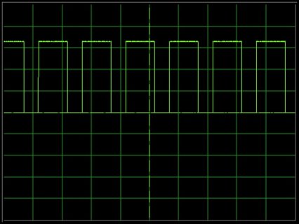
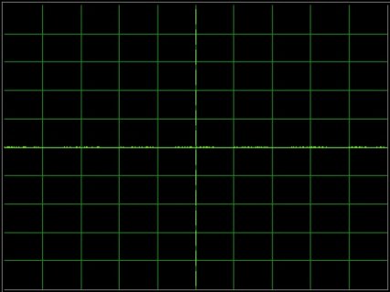
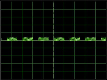
I checked with three different input Modes (V: 1.0 Volt/div H:200mS/div)
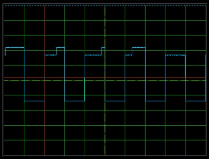
1) INPUT_PULLUP Same as before
Code:
void loop() { 
  pinMode(20,OUTPUT);
  digitalWrite(20,LOW);
  delay(100);
    
  pinMode(20,[COLOR="#B22222"]INPUT_PULLUP[/COLOR]);
  delay(200);
2016-10-08 15_18_24-Oscilloscope - NI ELVISmx.jpg

2) INPUT_PULLDOWN Nothing to see here... now move along.
Code:
void loop() { 
  pinMode(20,OUTPUT);
  digitalWrite(20,LOW);
  delay(100);
    
  pinMode(20,[COLOR="#B22222"]INPUT_PULLDOWN[/COLOR]);
  delay(200);
2016-10-08 15_22_01-Oscilloscope - NI ELVISmx.jpg

3) INPUT Note the 60hz line noise
Code:
void loop() { 
  pinMode(20,OUTPUT);
  digitalWrite(20,LOW);
  delay(100);
    
  pinMode(20,[COLOR="#B22222"]INPUT[/COLOR]);
  delay(200);
2016-10-08 15_24_30-Oscilloscope - NI ELVISmx.jpg
 
Last edited:
FWIW, with K66 and my cheap USB scope, I don't see such a glitch with OUTPUT/LOW then INPUT. I have 100 ms pulses at 1.66v. LED B is flashing.

with OUTPUT/LOW then INPUT_PULLUP, pulse height is 1.96v

I verified sketch could turn on LED A, B, A & B, and all off


ahh, i guess i need to test with LC... OK, no glitch with LC (pin 23), 100ms pulse, 1.64v
 
Last edited:
Status
Not open for further replies.
Back
Top