Teensy 3.6 Power supply

Status
Not open for further replies.

ToPi

Member
Hi everybody,

the freshly released Teensy 3.5/3.6 seems to be a great device! I am so happy to see a Teensy with integrated SD-Card!
I apologize if I missed it, but I did not find any information about power supply of the board and about how much current devices supplied by Teensy 3.5/-6 can draw from the board?
I would like to supply several MPU9250 sensors(max ~20mA each) and an ESP8266 WIFI module (which can draw up to 250 mA).

Can anyone give me a hint if this is feasible using the onboard power regulator?

Tobias
 
ToPi, if you have one of these boards in hand already, you should have recieved an information card with it that has a note about max current draw. If you don't have one yet, see this post for more information while Paul works on getting the information into the website. Click on the card info images.

Basically, the on-board regulator is rated at 250mA by PJRC, though the regulator itself is capable of a bit more draw but there wasn't enough room for sufficient heat-sinking to reach those ratings. Keep in mind the board itself draws some of the power by itself. Paul wrote this note when he released the Teensy 3.2, which uses the same voltage regulator as on the 3.5/3.6 as far as I am aware:
Version 3.2 is a minor upgrade to Teensy 3.1. The main change is an improved 3.3V regulator, to allow Teensy to directly power ESP8266 Wifi, WIZ820io (W5200) Ethernet, and other power-hungry 3.3V devices.

We're specifying Teensy 3.2's power output at 250 mA and the maximum voltage input at 6 volts, due to PCB thermal dissipation limits. However, the actual regulator chip is capable of up to 10 volts input, and up to 500 mA output. These higher limits are intended to allow Teensy 3.2 to be more rugged when used with non-USB power sources which aren't well regulated 5 volt sources.
 
A single current spec for the 3.3V output is difficult, so we print 250 mA as a sort of conservative compromise for the sake of simplicity.

The main issue with more current is temperature rise in the voltage regulator due to heat dissipation. There are more vias and a larger ground plane area on the internal layers on Teensy 3.5 & 3.6. If you try pushing the limits, pay attention to how hot the regulator gets.
 
I am probably going to consider external power sources...

I´m interested in external power sources as well, but I don't know how to start? Could you help me? What parts do I need, or can you recommend a tutorial?
About the mA limits: Am I right that those limits can be ignored with external power supply?

Thank you!

PS: Teensy 3.6 as well.
 
GP, a bit of conext would be helpful there in terms of what you are trying to do (1Amp, 100Amp)

Normally solution would be to use a regulator https://en.wikipedia.org/wiki/Voltage_regulator exact nature depending on input and current draw. And yes if getting current from somewhere else the 250mA limit is not in force, though do watch for how much you sink/source through the pins (LED powered from a pin comes from Teensy power budget, not the PSU).
 
I'm building a MIDI Controller with approximately 45 RGB Leds, 20 single Leds, 128x64 OLED Display, multiple DIN MIDI Connectors and of course many Buttons and Faders.
My main goal is, to make it standalone with no USB connected.

So I slowly understand that I need a "DC barrel jack", a PSU, and cut the VUSB and VIN on the backside from teensy. But how to connect it properly and where to put the voltage regulator you mentioned?
And if I use it with a 5V PSU, can I power everything between 3.6V and 6V from the VIN Pin (because of Teensy's regulator)?
 
And if I use it with a 5V PSU, can I power everything between 3.6V and 6V from the VIN Pin (because of Teensy's regulator)?
Teensy's regulator is the one limited to a 250mA output, so no, you should not draw more than ~250mA from the Teensy. It simply cannot drop a 5V input to 3.3V without thermal issues (all the extra voltage becomes heat in a linear regulator) at such amperages. If you need more 3.3V power than that, you must provide an external voltage regulator of some sort, cut the trace between VUSB and VIN (if you ever think the USB might be connected while your voltage regulator is), and apply the output of your 3.3V regulator to one of the 3.3V pins on the Teensy, and ground to ground (this can be done directly soldered to the board, via a barrel jack or other connector, or any other method you prefer). Then you are in effect bypassing the Teensy regulator altogether and the current draw restrictions do not apply (other than not exceeding the maximum draw from any I/O pin as mentioned by GremlinWrangler).

Watch out for "wall wart" power supplies, many are not adequately regulated to power a Teensy without causing trouble, you need a clean 3.3V power supply. A computer power supply (ie an ATX supply) would work though. It depends on the actual amperage load of your various LEDs and such. If under say 1A, there are a variety of linear regulators you can buy that only need a couple of capacitors added to be stable, though you still need to feed THAT power.
 
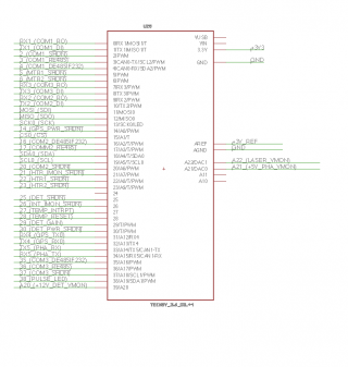
I am having some issues powering a Teensy 3.6 from an external source. I have the T3.6 mounted as a daughter board on a larger PCB, and am providing 3.3V to the 3.3V pin using a switching regulator. The T3.6 ran fine when powered from the USB port, but once I cut the VUSB trace and plug it into the main board it no longer runs. I have checked, and it is getting 3.3V from the main board. Any suggestions on what I am doing wrong?
 
Yup - I have GND and AGND tied to the ground plane. The schematic for the T3.6 pins is attached.
Screen Shot 2017-01-31 at 11.38.53 AM.png
 
the only thing i did is power teensy 3.5 with 5v on VIN, but i never cut the trace. I actually just use a "data-only" USB cable which doesnt contain the VCC (red) wire, OR, if none are available, I strip the shield off a cable and cut the red wire. At least this makes it easier to remove and test the teensy later on.
 
I don't think you put power through out puts like the 3.3v pins. You power through the 5v in. You can add 5v or 3.7v to that in though. If you are trying to power something off the teensy like a TFT use the 3.3 out with a 5v or 3.7v battery going though the Vin
 
Last edited:
If you have 3.3V only you should be able to power in via the 3.3V pin, say if you have a battery+boost circuit and don't want to have the onboard reg wasting power. You do have to be really careful that you can't exceed 3.3V if you do that though. The simpler design is to provide 5V to vin and let the regulator do it's thing if you already have 3.7-5.5V available in your design though.

looking at https://www.pjrc.com/teensy/schematic.html the only thing the Vin does is power the slave USB port on the 3.6, so that won't magically get 5V if only 3.3V is powering the board.

Just wanted to expand a little bit on GremlinWrangler's response:

On Teensy 3.5 and 3.6 the incoming USB +5v power goes directly to pin Vusb, then through a cut pad to pin Vin, then through a fuse to the LP38691 voltage regulator that supplies the rest of the board. The LP38691 accepts 2.7v - 10v input, so the easiest (best under most circumstances) way to power the teensy from a separate regulated power supply is to cut the trace between the cut pads and supply your input power to pin Vin. This isolates the USB power line and pin Vusb from the rest of the board, and still allows you to feed the teensy with power through the normal path.

You can feed Vin with 3.3 volts if you wish. However, if you feed Vin with less than 5 volts, you will have less than 5 volts on the V+ line of the secondary USB port, and if you feed Vin with less than about 4.2v you will power the Teensy with less than 3.3v (dropout voltage of the LP3869x is listed as 500 mV @ 500 mA, but I measured a voltage drop of about .9V on my bench with only the Teensy as a load, so an order of magnitude off from the datasheet). The purpose of the secondary USB port is to let the Teensy serve as a USB host, rather than the way it is typically used, as a USB slave. I haven't seen many people using it this way so far, and unless you need it in your design, I would ignore that aspect of any voltage limitation. The Teensy will run with much less than 3.3 volts, but it's technically a form of overclocking so you have to know what you're doing.

Now turning to the issue of whether it is OK to feed the teensy power through the pin marked 3.3v. The answer is once again that you can get away with it if you really know what you are doing, but there are a number of downsides to doing so.

Power from Vusb / Vin goes through a fuse, ferrite bead, polarity protection diode, input filtering capacitor, voltage regulator, output filtering / loop stabilizing capacitor, and THEN to the 3.3v pin and the teensy power rail. If you supply your power directly to the 3.3v pin, you will bypass all of that protection and filtering, and your power will go directly to the chips.

As GremlinWrangler points out, the only advantage would be that you avoid the slight power cost of the LP38691 regulator (and the heat associated with it).

The disadvantage would be that all the chips on your teensy board will be dependent on whatever filtering and protection your separate supply can provide, plus whatever else you add into your circuit design. If your PSU has ripple and switching spikes on the output, that may cause gremlins to appear in your device. Or if another board being powered from the same supply creates voltage spikes/sags/digital noise on the power rail, all that stuff is going directly into the chips on the teensy. For example, if you power a motor driver board from your external supply, you'll very likely see problems if you feed the teensy with that same contaminated power and no voltage regulation / filtering. There's a reason that commercial electronics devices contain multiple voltage regulators, each dedicated to a specific part of the system and tailored to a specific set of requirements. Analog Devices has some examples showing as many as 20 voltage regulators in a single device.

I should point out that the power routing described above applies only to the Teensy 3.5 and 3.6, whose power routing is a significant improvement over the same routing on the teensy 3.2 board. On the 3.2, power comes from the USB +5 volt line through the fuse before it gets to the Vusb pin and a capacitor to ground. Then it goes through a cut pad to the regulator and the Vin pin.

The old 3.2 routing turned out to be a sneaky problem for me because I wanted to take some power from the Vusb pin. That pin came *after* the fuse, and the fuse has a resistance of 0.3 ohms. The resulting voltage drop put the voltage outside the USB specification range, so my (USB compliant) device shut it down right away. Also, there was no polarity protection on the 3.2 boards, and supplying power from Vin bypassed the fuse. I modified several of the 3.2 boards to get around these issues, and it's very nice to have it sorted properly on the 3.5 and 3.6 boards!!

:cool:
 
Last edited:
One more suggestion. The OP was "looking for" a separate power supply, so this might be relevant: I use the AdaFruit PowerBoost boards to provide clean 5v power for my Teensy-based projects that include multiple other power-hungry boards.

The PowerBoost boards include both an MCP7381 (load sharing and LiPo battery charge management controller) and a TPS61090 boost converter. These boards automagically handle battery charging as well as hot-switching between a LiPo battery source and a connected external USB-style power source. This means you can hot-plug either/both the battery and a dirty external power supply, and the regulator continues to provide a rock-solid 5.2v of nice clean power as it switches back and forth, plus it smart-charges the battery whenever there's sufficient power to do so.

I just cut the power pad on the Teensy and connect the 5v PowerBoost output to Teensy pin Vin (not the 3.3v pin !!!)

There are several PowerBoost models, one of which can provide a full 1000 mA or more of current at 5.2v (from an appropriate battery or external supply). Very affordable for prototyping, too! :cool:
 
I wanted to revisit this separate power supply issue. If I power the Teensy with 3.3V (clean regulated power) on the 3.3V pin the Teensy won't execute the sketch it is programmed with. However if I plug it into a USB port, upload my sketch (in this case 'blink') it will run, then I can unplug the USB port and it will continue to run. From the schematic, I can't see why this is the case? The Teensy is 3.3V device, so it seems a little disappointing that we can't power it off the same 3.3V supply that all the other devices in our system run on.
 
I wanted to revisit this separate power supply issue. If I power the Teensy with 3.3V (clean regulated power) on the 3.3V pin the Teensy won't execute the sketch it is programmed with. However if I plug it into a USB port, upload my sketch (in this case 'blink') it will run, then I can unplug the USB port and it will continue to run. From the schematic, I can't see why this is the case? The Teensy is 3.3V device, so it seems a little disappointing that we can't power it off the same 3.3V supply that all the other devices in our system run on.

In my experience, you can indeed power the Teensy 3.2 with 3.3 volts. I suggest you do so by cutting the designated jumper and applying power to Vin rather than to the pin marked 3.3v.

I have done this with success, and have even seen the Teensy wake up and run with voltages below 3V, well below the specified acceptable range.

If the teensy doesn't start a loaded program when you cut the jumper and apply 3.3v to Vin, my first suggestion is to carefully assess the voltage at various points in your overall circuit. I've seen problems caused by unexpected voltage drops across seemingly innocuous fuses and small traces. If you still haven't found the answer to your particular problem, post your entire circuit schematic and people will attempt to help.

good luck!

-- Craig
 
Hello all
I need to decide a power regulator of 12 - 5V to power my circuit which includes Teensy 3.6 and other stuff. I can't find the upper limit to the current consumed by teensy 3.6 at 5V anywhere. It would be of great help if I could get that upper limit. And same current consumption details for teensy 3.2 would be helpful.
Thanks in advance!
 
There are notes - my recall is this in general - perhaps the K66 beta thread or the T_3.2 announcement area showing the LDO is rated at 250 mA for normal usage - that figure is stated on the Teensy Card for T_3.2/3.5/3.6.

They use the same LDO. The LDO can put out more current than 250 mA making more heat - depending on how much incoming voltage it has to burn off. There are resetting fuses on the Teensy board to limit current - that value may be in one of those threads.

The card shows VIN range is 3.6V to 6.0V - the closer to 3.6V the more current the LDO will pass before thermal shutdown. If you find the above thread notes on the exact LDO it will show it can do some 500 Ma or so.

If you look at those threads (K66 an/or T_3.2) and find the posts it would be good to link them here for others to find.
 
Last edited:
From the 3.2 announcement:

Teensy 3.2 is a minor upgrade to Teensy 3.1. The main change is an improved 3.3V regulator, to allow Teensy to directly power ESP8266 Wifi, WIZ820io (W5200) Ethernet, and other power-hungry 3.3V devices. We're specifying Teensy 3.2's power output at 250 mA and the maximum voltage input at 6 volts, due to PCB thermal dissipation limits. However, the actual regulator chip is capable of up to 10 volts input, and up to 500 mA output. These higher limits are intended to allow Teensy 3.2 to be more rugged when used with non-USB power sources which aren't well regulated 5 volt sources. Teensy 3.2 is fully compatible with all shields and add-on boards designed for Teensy 3.1. It preserves the same size, pinout, and processor as Teensy 3.1. The bootloader chip is also changed from Mini54 to KL02 (the same as Teensy-LC). The location of the reset pin and USB D+/D- pads underneath the Teensy changed between 3.1 and 3.2.
 
I wanted to revisit this separate power supply issue. If I power the Teensy with 3.3V (clean regulated power) on the 3.3V pin the Teensy won't execute the sketch it is programmed with. However if I plug it into a USB port, upload my sketch (in this case 'blink') it will run, then I can unplug the USB port and it will continue to run. ...

Check setup() for something like : while ( !Serial )
If it has code like that it would explain what you see. It won't leave that while() until USB is activated. When USB generally desired - but not required something like this works well - in this case it waits up to 4 seconds and then continues: while ( !Serial && millis()<4000 )

Yup - I have GND and AGND tied to the ground plane.

AFAIK: The AGND is meant to be separate clean ground from AGND and shouldn't be tied together
 
Status
Not open for further replies.
Back
Top