SPI Mode Confusion

Status
Not open for further replies.

madmattd

Well-known member
I'm finally getting back to a Teensy-based datalogger project of mine. Among other sensors, one I am using is the ITG-3701 from Invensense. Here is the datasheet and here is the register map.

My confusion stems from the SPI Mode. I've included a few snippets from the datasheet below:
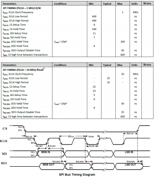
ITG-3701_SPI_Details.PNG
And from page 19 of the datasheet:
SPI Operational Features
1. Data is delivered MSB first and LSB last
2. Data is latched on rising edge of SCLK
3. Data should be transitioned on the falling edge of SCLK
4. SCLK frequency is 1MHz max for SPI in full read/write capability mode. When the SPI frequency
is set to 20MHz, its operation is limited to reading sensor registers only.

From the image, I take it to mean that CPOL=1 as it looks like it wants the clock to idle high. And from the text quoted above, it looks like CPHA=1. So, SPI mode = 3. Except no, only SPI mode = 0 reads back a non-zero value for the who_am_I register, for example (and on mode 0 it returns 0x68 as expected. With SPI mode = 0, I then derrived the below code, which plots nicely on the serial plotter (my first time using it!), and gives fairly reasonable results as I rotate the board along the various axes.

Code:
#include <SPI.h>

// prints data to serial monitor, without labels for use with Serial plotter.
// written 23-Oct-2016

const byte ssPin = 19;  //chip select pin
SPISettings GyroSettings(1000000, MSBFIRST, SPI_MODE0);

void setup() {
  // put your setup code here, to run once:
  pinMode(ssPin, OUTPUT);
  digitalWrite(ssPin, HIGH);
  Serial.begin(9600);
  while(!Serial){}
  SPI.begin();
  Serial.println("Connected");
  
  SPI.beginTransaction(GyroSettings);
  digitalWrite(ssPin, LOW);
  SPI.transfer(0x75 | B10000000); // send who_am_I with read flag set
  Serial.print("Who am I: ");
  Serial.println(SPI.transfer(0), HEX);

  SPI.transfer(0x26); // send write command to register 26
  SPI.transfer(B00000001);  // send data to write to register 26 - 184Hz bandwidth)

  SPI.transfer(0x27); // send write command to register 27
  SPI.transfer(B00001000);  // send data to write to register 27 - 1000dps scaling

  
  digitalWrite(ssPin, HIGH);
  SPI.endTransaction();
}

void loop() {
  // put your main code here, to run repeatedly:
  int16_t tempInt = 0; // temporary integer for assembling data bytes
  SPI.beginTransaction(GyroSettings);
  digitalWrite(ssPin, LOW);

  //Serial.print("  X: ");
  SPI.transfer(0x43 | B10000000); // issue read command for register 43, the GYRO_XOUT_H
  tempInt = int16_t(SPI.transfer(0) << 8);
  tempInt += SPI.transfer(0);
  Serial.print(tempInt / 32.8);
  tempInt = 0;

  //Serial.print("  Y: ");
  Serial.print(" ");
  tempInt = int16_t(SPI.transfer(0) << 8);
  tempInt += SPI.transfer(0);
  Serial.print(tempInt / 32.8);
  tempInt = 0;

  //Serial.print("  Z: ");
  Serial.print(" ");
  tempInt = int16_t(SPI.transfer(0) << 8);
  tempInt += SPI.transfer(0);
  Serial.println(tempInt / 32.8);
  tempInt = 0;
  
  digitalWrite(ssPin, HIGH);
  SPI.endTransaction();

  delay(100);
}

So what am I missing? Surely SPI modes aren't different on Teensy, are they?

EDIT: I guess I should mention this is a Teensy 3.2-based board, currently using Arduino 1.6.12 and Teensyduino 1.31beta1, on Win10Pro.
 
Last edited:
That:
Code:
  SPI.transfer(0x75 | B10000000); // send who_am_I with read flag set
looks suspicious...
Usually, there is no read-flag for SPI.
 
That:
Code:
  SPI.transfer(0x75 | B10000000); // send who_am_I with read flag set
looks suspicious...
Usually, there is no read-flag for SPI.

Interesting, usually there has been for the sensors I've used, such as this and a number of ST accelerometers and gyros. It looks like I clipped part of the quote above, here is number 5:
5: SPI read and write operations are completed in 16 or more clock cycles (two or more bytes). The
first byte contains the SPI Address, and the following byte(s) contain(s) the SPI data. The first
bit of the first byte contains the Read/Write bit and indicates the Read (1) or Write (0) operation.
The following 7 bits contain the Register Address. In cases of multiple-byte Read/Writes, data is
two or more bytes:
 
hm, ok. i've only used other SPI-Chips, like RAMs and FLASH before. they use different commands for read and write.
but did you try it without the flag ? i guess "whoami" is read-only anyway..
 
Last edited:
Ah yes, Flash chips don't need the flag. Probably because read and write are explicit separate commands, whereas sensors have all these configuration registers and so just have the high bit to indicate read/write. I have a Spansion SPI flash chip in this project too... currently trying to port everything over to use SPI transactions while I am getting this thing working, especially given this gyro needing a lower bus speed for writing.

No SPI mode works without the read flag, it returns 0x00.
 
Sending the who_am_i command looks correct to me given the description in the datasheet.
I would try that with each of the SPI modes and hope that one of them returns something sensible :)

Pete
 
I would try that with each of the SPI modes and hope that one of them returns something sensible :)

I guess I wasn't quite clear enough. I did just this, anything but SPI Mode 0 returns 0x00. Mode 0 returns 0x68, which is correct according to the datasheet.

My question is WHY, when the documentation suggests to me that it ought to be a Mode 3 device. Perhaps I have mis-interpreted the datasheet and/or the SPI mode table?
 
I misread/misunderstood your post. I agree that the datasheet indicates that the clock idles HIGH and so the mode should be 2 or 3. The manual for the K66 also indicates that CPOL=1 when the clock idles HIGH so it's almost certain to be the same for the T3.2 processor.
But it works with mode 0. Go for it :)

Pete
 
Well, I have something broken in my setup I'd say. A sensor that I've used a fair bit in the last couple of years and I am 100% positive is a Mode3 device (datasheet says so, internet agrees, and it is the only mode I've gotten to work across multiple different Arduino-compatible processors) no longer works on Mode3. Mode0 returns a valid result from who_am_I, but all zeros for the data output, no matter what tilt or bumps I give it. This is a simple breadboard setup that I've done many times before (though it has been a few months), just a Teensy and a breakout board for the chip that I have used many times before (it worked with a Teensy 3.2 and an LC earlier this year). It doesn't even work with a 3V3 8MHz 328p setup! What am I missing? A corrupted setup somehow? (I fully flushed and re-built this Arduino install a few weeks ago). Something else? This is such a simple test, I am just not seeing where the issue is this week with SPI-land. Hopefully something stupid?

H3LIS331DL Datasheet

Code:
#include <SPI.h>

// prints data to serial monitor, without labels for use with Serial plotter.

const byte ssPin = 10;  //chip select pin
SPISettings AccelSettings(1000000, MSBFIRST, SPI_MODE0);

void setup() {
  // put your setup code here, to run once:
  pinMode(ssPin, OUTPUT);
  digitalWrite(ssPin, HIGH);
  Serial.begin(9600);
  while(!Serial){}
  SPI.begin();
  Serial.println("Connected");
  
  SPI.beginTransaction(AccelSettings);
  digitalWrite(ssPin, LOW);
  SPI.transfer(0x0F | B10000000); // send who_am_I with read flag set
  Serial.print("Who am I: ");
  Serial.println(SPI.transfer(0), HEX);

  SPI.transfer(0x20); // send write command to register 20
  SPI.transfer(B00111111);  // send data to write to register 20 - normal power mode, 1000Hz, enable all axes

  SPI.transfer(0x23); // send write command to register 23
  SPI.transfer(B10000000);  // send data to write to register 23 - 100g scaling

  
  digitalWrite(ssPin, HIGH);
  SPI.endTransaction();
}

void loop() {
  int16_t tempInt = 0; // temporary integer for assembling data bytes
  SPI.beginTransaction(AccelSettings);
  digitalWrite(ssPin, LOW);

  // X
  SPI.transfer(0x28 | B11000000); // issue read command for register 28, with read and increment flags set, the OUT_X_L
  tempInt = int16_t(SPI.transfer(0));
  tempInt = (int16_t(SPI.transfer(0) << 8) + tempInt) >> 4; // read OUT_X_H, and assemble
  Serial.print(float (tempInt / 49.0));
  tempInt = 0;
  
  // Y
  Serial.print(" ");
  tempInt = int16_t(SPI.transfer(0));
  tempInt = (int16_t(SPI.transfer(0) << 8) + tempInt) >> 4;
  Serial.print(tempInt / 49.0);
  tempInt = 0;

  // Z
  Serial.print(" ");
  tempInt = int16_t(SPI.transfer(0));
  tempInt = (int16_t(SPI.transfer(0) << 8) + tempInt) >> 4;
  Serial.println(tempInt / 49.0);
  tempInt = 0;
  
  digitalWrite(ssPin, HIGH);
  SPI.endTransaction();

  delay(100);
}
 
Status
Not open for further replies.
Back
Top