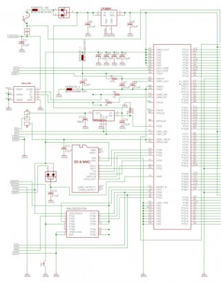
Teensy 3.5 & 3.6 Schematic Posted

Status
Not open for further replies.
I just right-click and 'Save Image As'. The image names are close enough to be used as file names, except for the T1 boards.
 
I you're using windows 10, you can open the imag in a new browser-window and use "print to pdf".
(Or use any other "pdf printer")
 
Hello everyone,

I'm using a Teensy 3.6 for my project (amazing board, thank you Paul!), now I'm trying to recreate this board with a different layout by asking a company to de-solder the components from the board and re-solder onto my layout. Although I haven't used all the pins in my prototype, I decided to redraw the whole schematic of the board in Eagle so that others could use it as well.

So far I've made the library for MK66FX1M0VMD18 micro-controller based on the Teensy 3.6 schematic (the pins which weren't used in Teensy are not drawn in the schematic). I've double checked the connections, but as I'm no pro, it's worth to triple check it yourself :)

There are a couple of noobie questions I have:

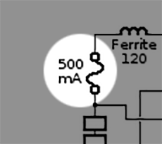
1. What element does this symbol represent?
unknownSymbol.gif

2. Is there any difference whether I use e.g. an 0805 capacitor or an 0402?

I would also appreciate any advice or comments regarding the approach I've chosen (it's my first time).

Another micro-controller I needed for my project was Simblee, I've also made its Eagle library (in case anyone Googles!).
 

Attachments

  • MK66FX1M0VMD18_eagle_library.zip
    3.5 KB · Views: 184
  • simblee_eagle_library.zip
    2.4 KB · Views: 156
That component may not be what you think it is, so should probably wait for Mr. Stoffregen to reply.
 
Just asking here, but why go to the trouble of desoldering the components rather than just purchase new ones? It seems like a lot of trouble/expense. Especially a BGA part.

I had a local company replace a BGA for me a year or so ago, it took them a week and cost £60. I don't think it would have cost as much to solder a fresh one to a new board. If you can use a QFP part for your project, you could solder it yourself with a fine tip soldering iron (being very careful).

Regarding the passive components, the obvious difference is the size. If you're soldering them by hand, 0805 are easy, 0603 are ok too with tweezers and being careful not to sneeze, but 0402 are really small. Personally I'd avoid them unless really short on board space.

The other big concern is their ratings. E.g. for resistors, the larger sizes can usually sink more power, so check the datasheets of the parts you use to ensure you're not going to fry them.

Hopefully others can chip in here with their experience of board designs. It's not something I do often.
 
Oh, forgot to add. Have a look on youtube for videos on soldering surface mount components. There are some good tips on there.
 
Yes, I'd buy new parts, too. Esp. if you want to make more than one board.
You have to buy only the bootloader from PJRC.
I just ordered some. Currently, I don't have an exact plan, but I want to design my own board in the future. Don't know, when..
 
Last edited:
Thank you for your responses :)

...why go to the trouble of desoldering the components rather than just purchase new ones? It seems like a lot of trouble/expense. Especially a BGA part.

My main reason for such decision was the MK66FX1M0VMD18 micro-controller. I wasn't sure whether I could simply put a new one in place. Thanks to Frank B, I'll read more on bootloaders to get a better understanding. As for other parts, I'm OK with getting new parts; except for the "fuse" part in discussion, which I figured is a custom component. I believe it's the one shown below:
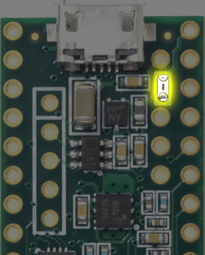
500mA_fuse.gif

Here's also the little progress I've made:
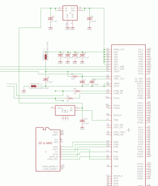
teensy3.6_wip01.gif

The microSD schematic is from Adafruit's library. I've also attached the libraries I made for LP38691 and TPD3S014. Please make sure they are correct before using them!

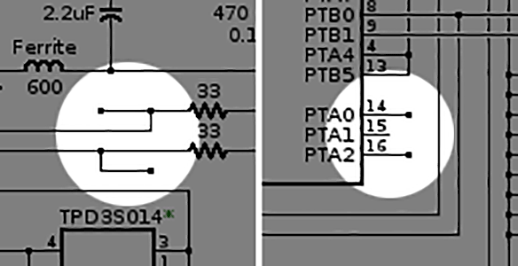
So far, those two "floating junctions" next to 33 Ohm resistors (R2 and R3) have caught my attention, what's their purpose?

And one part I haven't been able to find its datasheet, is the "double diode". I think these two are the ones:
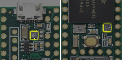
parallelDiodes.gif

In the pinout image above, I see "AN w63" written on them (the little circle seems to be their orientation indicators). On my Teensy though, the numbers are 66.

Thanks again :)

Update (May 6th, 2017): Fixed some issues with the layout of attached libraries (redrew TPD3S01's layout based on SOT-23-6 package, and the orientation indicator of LP38691 is now a circle).
 

Attachments

  • LP38691.zip
    1.4 KB · Views: 163
  • TPD3S014.zip
    1.3 KB · Views: 168
  • LP38691_updated.zip
    1.4 KB · Views: 180
  • TPD3S014_updated.zip
    1.3 KB · Views: 165
Last edited:
Fuse is not custom. Only the external bootloader chip is custom to PJRC to be a 'Teensy'.

Thank you. I picked this fuse for the board.


Most appreciated. I've attached the library I made off of its datasheet.

I'm almost finished. Working on the oscillators.
teens3.6_wip02.jpg

There are a couple of ambiguities. Mr. Stoffregen, could you please elaborate on these?

1. What's the purpose of these floating junctions?
floatingJunctions.gif

2. The total number of resistors, capacitors, inductors and the fuse sum up to 23 on the board, while only 21 of these components are present in the schematic. Am I miscounting any of the components?

Thanks to the great community :)
 

Attachments

  • PMEG4010CPA_double_diode.zip
    1.6 KB · Views: 151
1. What's the purpose of these floating junctions?

2. The total number of resistors, capacitors, inductors and the fuse sum up to 23 on the board, while only 21 of these components are present in the schematic. Am I miscounting any of the components?

ad 1) these are test points (to be used by PJRC)
ad 2) could you break down your counts?
also you know T3.5 has less components than T3.6
 
Am I miscounting any of the components?

Yes.

Perhaps you're counting the symbols for jumper pads as components? There are 2 of these, which allow you to separate VIN-VUSB for external power applications, and to connect the USB1 power pin differently (the default is power from the TPD3S014 chip).
 
Thank you. I picked this fuse for the board.
I think this is the wrong fuse type. It's a "one shot", non-resettable fuse which must be replaced once it has been activated (blown). The fuse used on Teensy is a resettable PTC/PPTC. Not confirmed, but I think it is Bourns MF-FSMF050X.
 
You could choose any type of fuse. Or leaving the fuse off is also an option. It really depends on the usage case for your PCB and whatever product or project you're building.

Teensy and Arduino and other hobbyist-oriented boards have this PTC fuse because of the experimental learning nature of their intended use.

Rather that directly copy every aspect of Teensy, you really ought to think carefully about what your own board really needs. Does your device really use 500 mA or power arbitrary other circuitry (as Teensy does) which could really use 500 mA?
 
Last edited:
There are a number of hidden gotchas in DIY Teensy, along with the resources you get on the bootloader page doing a search for

custom teensy site:forum.pjrc.com

Will get some of the stories that may be worth review about vbat, crystal traces and many other such things before you try and flash up your new board, and especially before posting questions.
 
Hi,
the schematic for teensy 3.5 states that the led is on portc bit5. since i want to use direct port access i tried to blink the led, i used ddrc/portc to access the pin. however as it turns out after some try and error, it is connected to portb bit5, so ddrb/portb works.
this should be corrected in the docs - i still have to try the other mappings...

Your test is faulty (DDRB is AVR-speak). LED is on pin 13 PORTC bit 5. the following toggles the LED
pinMode(13,OUTPUT);
for (int i=0;i<10;i++) { GPIOC_PTOR = 1<<5; delay(1000);}
 
Status
Not open for further replies.
Back
Top