Teensy Audio Adapter and Audio Library - Stream mic to serial USB interface

Status
Not open for further replies.

alonper

Well-known member
Dear Friends,

I would like to know if there's an option for streaming the mic signal data to the USB serial interface and receive it in the PC
Is the Teensy 3.0 + Audio adapter can be good for me?
I see that each Audio adapter has 2 input channels. Can I connect in parallel TWO audio adapters? (I need to stream 3 mics to the computer)
What it the bandwidth of the serial USB interface? it is enough for 3 16bit 44.1Khz channels? (705,600 * 3 bps)

If there's any project of streaming to the PC the mic signal i will be happy to see! :))

Thanks in advance for any help.
Alon
 
Will do most of what you want to do.

You can stack two boards with a bit of fiddling, and there is the USB IO option. See the Audio example USBPassThrough which is doing the reverse of what you want to do.

You can probably actually use one board if you wire things right, since there is 2 line ins + a microphone connection so if you can condition your signals right you have three potential access points.

Suggest having a read through
http://www.pjrc.com/teensy/td_libs_Audio.html

And links to get a better idea of what you can and can't do, my main thought at the moment would be your audio quality which is generally good but not amazing depending on how things get wired.
 
Hi GremlinWrangler, Thanks for your fast reply.
I will start my research.. I have looked over the USBPassThrough but it looks that its not implemented..

You can probably actually use one board if you wire things right, since there is 2 line ins + a microphone connection so if you can condition your signals right you have three potential access points.
Did you meant that I should use only one Audio Board and another mic to connect to one of the based analog input of the Teensy?, or I that I should connect 2 Audio Boards?
The USB serial interface is enough for streaming the 3 channels? (more than 2.1 Mbps)

Regarding the quality, Actually I need to keep the best quality I can. And for that I need to make the same modulation and convertion to all the channels (because I am going to analyze and compare all the 3 mics - its 3 Piezo sensors that receive wood vibrations)..

One more question -
I have two pieces of sparkfun PCM1803a ADC breakout board https://www.sparkfun.com/products/retired/9365
I really wanted to use them because of the great quality (24bit 96Khz - 2 channels each)
Do you know if I can connect this boards to the teensy and how? is the Audio System Design tool can help me with that?
If you have seen some project that also use external Audio board I will be glad to see

Thanks a lot!
 
Hi Paul!
My mistake, somehow I erased part of the code :eek:, I tried to open it again and I see it.
Sorry for that. I still a noob in this business..

mmm... What does this USBPassThrough? Its stream a file from PC through the teensy USB serial interface to the audio board output?

Actually I cant test it, because I still didnt got the Teensy 3.2 and the Audio boards..I have open this post because I would like to understand how should I make it and what exact hardware I need to order. I really sorry for the noob questions.. no experience in this area.

Currently I have only the Teensy 2.0 and Sparkfun PCM1803a, Do you think that I can make it with this boards?
 
The SGTL5000 codec on the audio shield has 2 ADCs and can handle either a stereo line input OR a microphone, but not both simultaneously. So, you would need 2 audio shields, and 2 of the microphones would have to be amplified somewhat before being fed in to the stereo line inputs of one of those audio shields.
 
What about the bandwidth of the serial USB interface?
it is possible to stream over 3Mbps from the Teensy to the PC?
 
What about the bandwidth of the serial USB interface?
it is possible to stream over 3Mbps from the Teensy to the PC?

Well, there's sometimes a difference between what's technically possible, and what is achievable within a certain amount of time & effort & skill level.

But before going into that, I need to point out you've specifically asked about "the serial USB interface". The USBPassThrough doesn't use USB serial. It uses USB audio. There's a mention of this in the code:

Code:
AudioInputUSB            usb1;           //xy=200,69  (must set Tools > USB Type to Audio)

Sounds like you don't yet have a Teensy, but you're using Arduino with Teensyduino, right? At least take a moment to look at that Tools > USB Type menu.

When you program a Teensy with USB Type set to Audio, Teensy appears to your computer as a USB sound device, *not* a USB serial device. This is important, first because the PC side drivers need to see an audio device. It's also important because USB has 4 different transfer types. USB serial uses "bulk" and USB audio uses "isochronous". To learn more about these, please refer to the USB spec. Here's a direct link, to save you time digging around www.usb.org.

http://www.pjrc.com/teensy/beta/usb20.pdf

The transfer types are explained starting in section 4.7 on page 20. If you're going to talk about USB programming, it's essential to read chapter 4 and the first part of chapter 5. USB has a number of important concepts and very specific terminology. You really must read those chapters if you're going to have any sort of meaningful conversation about USB programming.

Now, back to the part about possible vs achievable. The reality is this is pretty advanced programming, to implement USB audio and manage isochronous streaming. The code is written to stream stereo in both directions (a total of 4 audio channels running simultaneously, 2 in each direction, which adds up to 352.8 kbytes/sec sustained streaming). This has been well tested and definitely does work.

If you want to dive into the code which implements this, here it is:

https://github.com/PaulStoffregen/cores/blob/master/teensy3/usb_audio.cpp

I don't want to discourage you, but the reality is this is pretty advanced stuff. If you *really* want to jump into this code and tinker, you certainly can. But before you do so, and before you ask more USB programming questions here, please read chapter 4 and the data flow model stuff in chapter 5. You really *must* know at least that basic USB stuff to participate in any meaningful conversation about USB programming.
 
Hi Paul,

Thank you for links and explanations.
It seems that I really need to understand the USB principles and mechanism before doing any step.
Anyway, I will do my homework untill the Teensy 3.2 will arrive.. hopefully to get better understanding.
I guess that I will have more questions later on.

Thanks by now
 
The SGTL5000 codec on the audio shield has 2 ADCs and can handle either a stereo line input OR a microphone, but not both simultaneously. So, you would need 2 audio shields, and 2 of the microphones would have to be amplified somewhat before being fed in to the stereo line inputs of one of those audio shields.

1. About the preamplifier, I am using Piezo sensors - Do you have any example or recommended op-amp? do you think that the AD869x is good for that job http://www.analog.com/AD8694?doc=AD8691_8692_8694.pdf
2. Regarding the high frequencies, The Audio Board has LPF to remove all the frequencies above 22Khz for prevent aliasing?

Thanks.
 
@alonper: My experience is with instrumentation design in a Chemistry dept, but have never had to do any vibration analysis. But, from my music hobby, I know that piezo transducers put out more voltage than do other audio transducers such as microphones which are magnetic-based. So, they may be able to put out enough to work with the most sensitive SGTL5000 line input setting- 250 mV p-p or about 85 mV RMS. But, piezo sensors are generally high impedance devices. The SGTL line input is only 25K input impedance, which is lower than piezos normally need (100K +). So, you might need the op amp just to provide the high input impedance. The AD8691 looks fine for this purpose to me.
The SGTL5000/audio module does not contain any LP filtering, so your aliasing comments apply. I didn't think that high frequency sound propagated well through wood, but I don't have any experience with this.

Ok, thanks! I will try that, I am still waiting for my new teensy to arrive.
Regarding the LINEIN impedance, I am trying to understand what is the difference between the "MIC" input and the "LINEIN"?
 
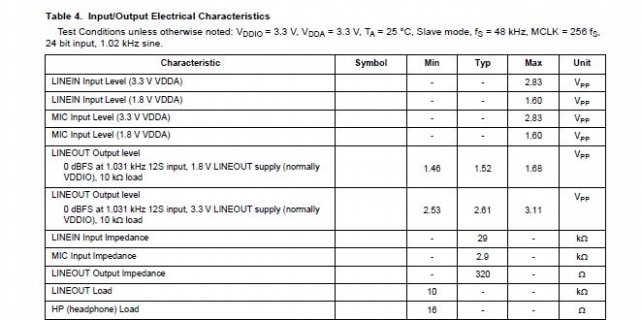
The MIC input impedance is much lower than LINE IN: 2.9K vs 29K for the LINE IN. But, the MIC input can have up to 100X the sensitivity of the LINE IN, depending upon settings in the SGTL5000 chip. The Audio library/Audio designer can be used to set both MIC and LINE IN sensitivity- the MIC setting is in dB whereas the LINE IN is specified in actual voltage levels (in the audio designer itself).
The MIC input also contains a bias resistor connected between the input and a stable DC voltage (1.25- 3.0 volts programmable) provided by the SGTL5000 chip. This is meant to provide the necessary excitation voltage needed by electret microphones, which are the cheap type mics usually used with the audio board. This may be harmful/unusable with your piezo sensors ?? I don't know what you are using.
 
But, piezo sensors are generally high impedance devices. The SGTL line input is only 25K input impedance, which is lower than piezos normally need (100K +). So, you might need the op amp just to provide the high input impedance. The AD8691 looks fine for this purpose to me.
The SGTL5000/audio module does not contain any LP filtering, so your aliasing comments apply. I didn't think that high frequency sound propagated well through wood, but I don't have any experience with this.

I didnt take in account the impedance matching...
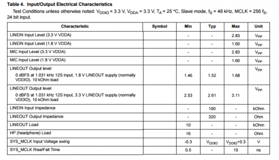
but I see in the SGTL5000 datasheet that the LINEIN impedance is about 100Kohm (or am I wrong?) , is that not good enough with piezo? how can I know what is the impedance of my piezo? I am using Piezo sensor of SHADOW SH 711, but i cant find any specifications...

Thanks again...
 
Page 6 of my NXP SGTL5000 datasheet shows 29k. Where does the 100k figure come from?
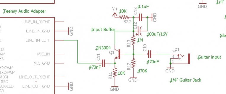
That Piezo pickup is for guitars, violins etc. and I expect it is high-impedance- all guitar amps have input impedances of several hundred K or more. I just built a Teensy-based digital guitar amplifier/effects unit and I put a one transistor buffer stage in between the guitar and the SGTL5000 line input to match impedances. This was for standard magnetic guitar pickups, but I think the same will apply for your piezo pickup. With magnetic pickups, if you feed them into a low impedance amp, the tone is muffled somewhat, and the strings are damped to some extent (along with the volume being lower than usual)
Hope this is helpful- I am not sure if you are doing something different with the piezo than what it is sold for.
 

Attachments

  • Capture.JPG
    Capture.JPG
    56.7 KB · Views: 186
:eek: I looked here http://www.pjrc.com/teensy/SGTL5000.pdf
page 6
LINEIN.PNG


I am trying to do the same, guitar connected to the audio board! but instead of the magnetic-pickup I am using this Piezo attached to my guitar..
Do you have any Git or a schem of your transistor buffer? or should I used the AD8691?
by the way I snipped the piezo with scope and it seems that he produce only 100mv p-p , and even less... :(
 
The 100 mv will likely be OK- the Line In of SGTL5000 is about 240 mv at most sensitive setting, so you will be getting a good percentage of that. Or, if you use the buffer, you could feed the MIC input and get lots of gain, as its lower impedance won't be an issue with the buffer ahead of it. Following is my buffer- coincidentally I was just drawing it up for an article I'm writing. This circuit provides a gain of only 1 (unity) but does the necessary impedance matching. The 2N3904 is a common transistor- not the lowest noise type, but works fine for a standard guitar pickup. You could also look on the web for buffers using a FET transistor, as they are also commonly used and probably a bit quieter. V+ can be a 9V battery or other clean 9-12V supply.
Capture3.JPG
 
Page 6 of my NXP SGTL5000 datasheet shows 29k. Where does the 100k figure come from?

Looks like we had the "Rev 5.0, 5/2013" version of the datasheet on the website.

I've replaced it with the "Rev 6.0, 11/2013" version.

Page 67 lists of the revision history. The changes for 6.0 are:

  • Modified front page intro text to include more target markets and to remove type of IC technology
  • Increased HP max output power from 45 mW to 62.5 mW at 1.02 kHz based on bench measurements
  • Changed TYP LINEIN input impedance from 100kohm to 29 kohm at 1.02 kHz based on bench measurements
  • Added MIC input impedance based on bench measurements
  • Removed 10 kohm MIN LINEIN input impedance, and added 29 kohm as TYP in Table 5 and Table 6
  • Added 12 kHz sample rate to Functional Description Introduction, and added 12 kHz and 24 kHz sample rates to Table 8

FWIW: the "type of IC technology" words removed from the first page were "This device is powered by SMARTMOS technology".

Edit: seems strange to think the audio library and audio board began over 3 years ago! I just looked at the old PCB files... my first SGTL5000-based prototype was sent to OSH Park on October 20, 2013. I did all the design based on the Rev 5.0 datasheet. The very first hacking of Node Red into the audio design tool happened nearly a year later, so it was really early 2015 when the audio library became usable.
 
Last edited:
Interesting. The 100k figure they initially quoted would match up with industry standards for HiFi component line input impedance. They probably published that before actually doing any measurements. I thought it was 100k myself, maybe from referring the PJRC link, until I double checked it in the PDF datasheet I had recently downloaded from Freescale/NXP.

@alonper- while I sent you the schematic of my buffer as you requested, in your case you would be better off using a circuit that runs on 5V, I expect, as that is all you have available (??) . My project had 20V available for the power amplifier, which I regulated down to 5V for the teensy/audio board, and 12V for the preamp.
 
Now, back to the part about possible vs achievable. The reality is this is pretty advanced programming, to implement USB audio and manage isochronous streaming. The code is written to stream stereo in both directions (a total of 4 audio channels running simultaneously, 2 in each direction, which adds up to 352.8 kbytes/sec sustained streaming). This has been well tested and definitely does work.

Hi Paul, It's been a long time since I asked this question - It took me a long time to dive in those things (much work in the university..)

I see in the object AudioOutputUSB that there are 4 channels :
audio_block_t * AudioOutputUSB::left_1st;
audio_block_t * AudioOutputUSB::left_2nd;
audio_block_t * AudioOutputUSB::right_1st;
audio_block_t * AudioOutputUSB::right_2nd;

So is it possible to patch 4 channels to 1 AudioOutputUSB 0,1,2,3 (same as AudioOutputI2SQuad)?
I can see here that there are only 2 channels (left & right).
If it's not possible, have you saw other project that makes the AudioOutputUSB to work with 4 channels?

Thanks a lot.
 
Hi Paul,
I am trying to dive into the USB specs (specifically chapter 5). In the meantime I am trying to understand the logic behind the usb_audio lib.
Any suggestion where to focus?
The Idea is to divide the buffer to 4 (instead of 2) and push the AudioStream (that will be configured to 4 inputs)?
Do I need ot make changes also in the AudioStream.h\cpp?

Thanks for any information you provide..
Best,
 
Why does the usb_audio_transmit_buffer set to array size 90 (AUDIO_TX_SIZE/2)?
I can see that usb_audio_transmit_buffer is uint16_t type, so why every callback you copy there 32bit? (right and left)
copy_from_buffers((uint32_t *)usb_audio_transmit_buffer + len,
left->data + offset, right->data + offset, num);

does something need to be changed in the USB_AUDIO definition in usb_desc.h? how does the os knows how many channels come from the device?
 
Is there a Teensy simulator with debugger that I can work with?
Or any idea how can I understand the flow of the program?
 
Status
Not open for further replies.
Back
Top