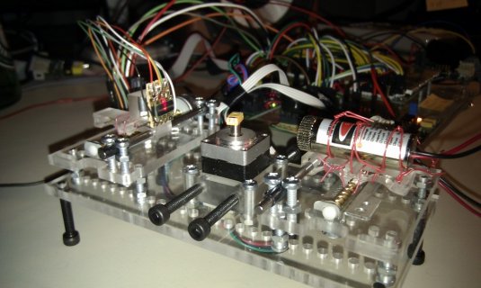
New library and example: Read-TSL1410R-Optical-Sensor-using-Teensy-3.x

Status
Not open for further replies.
Something that took me a bit to get my head around at the beginning, when thinking of filament handling ideas, is that it doesn't act like string. The cooled filament is rigid, so it is more like a thin, flexible rod. If you have a 12" straight piece and hold one end, the other end will only droop a little. To get a meaningful tension reading, the outer wheels would need to be several inches apart before the middle wheel would be able to displace it. On top of this, there is the fact that while one end is rigid and resists bending, the other end is melted and offers almost no resistance to stretching at all. So the tension at the puller doesn't change as the amount of plastic increases or decreases. When it increases, it doesn't reduce tension, it just bunches up, moving the excess plastic sideways, increasing diameter.

The tension control is useful for the other side of the puller, because the spool needs to stay in sync and adjust speed as the circumference of the spooled filament changes. Originally I was experimenting with using a separate puller to take up the dropped loop before I realized I could just make the spool do it. To keep the spool in sync, I ran the filament over a spring loaded arm which used a potentiometer shaft as its axle. The spool motor ran a PID routine with the potentiometer reading as the input, and ran at whatever speed was necessary to maintain a particular amount of tension- https://www.youtube.com/watch?v=En3bWu_PNB4
 
Perhaps I could buy a prototype having the puller-wheel mechanicals, and I could experiment with various PID width sensor / tensioner / arrangements in tandem with your efforts.

Do you have a basic filament puller-wheel mechanicals worked out yet, apart from the control loop issue? I would be happy to purchase a setup and tweak it.

Let me know. In the meantime, I will continue translating the Processing code.
 
Ok how about this, a pull sensor more akin to a digital fish scale, which tugs on the line length-wise? Then we are measuring the pull from the pulling wheel itself, but this wheel rides in a floating carriage on a shaft, and the pulling force stretches or compresses a string or moves a weight hung over a pulley, etc.

So the pulling wheel assembly is on a guide shaft, etc, and can glide towards the extruder or away as the pull force changes, and we measure this displacement to derive the tension. Then as before, another sensor could be looking at the thickness for sake of absolute mm control.

Some such scales have Bluetooth so you could just get data and be done with it, but I am still looking for cheaper ones in the low weight range.

The main concern with these is sensitivity for small pull forces, and speed (sampling rate)

Another option is a load cell with a circuit board with Serial or SPI out, or Bluetooth out.

Heck, you could just select a tiny "hanging load cell", or a "strain gauge", and read it's analog out on Arduino.

see
http://www.robotshop.com/blog/en/interfacing-a-load-cell-with-an-arduino-board-16247

That load cell is probably too big for your application, but it shows how some folks use them with Arduino.

I don't know if it could be rigged to measure a pulling force, but that's a nice idea perhaps.

You need a very low-force model to make the accuracy good, yah.

Maybe your potentiometer on a spring lever is not so bad a thought after all. Maybe use a linear pot to replicate the action of the fish scale.
 
Last edited:
I found this interesting and informative; he mentions that the way the pros get a given diameter is by applying a certain steady corresponding pulling force, and explains the art of making filament professionally.

How It Is Made: 3D Printing Filament

a couple interesting things..

They are extruding very fast, so the water tanks and catenary are very large length-wise ...

They use a "traction wheel" mechanism to pull and precisely control the diameter of the filament.

Is it mounted on a linear slide to cushion variations in tension with more dynamic precision than wheel torque alone?
(I could not put the linear rail slide in context due to each part of the system being shown separately.)

I saw a similar idea applied in coil winding machine. The take-up wheel can actuate on a linear slide very crisply to respond fast and precisely to changes in tension.

Heh, maybe you can simply use the filament tension on the take-up wheel carriage to vary the droop in a wire with a weight attached to it's center, to re-gain that preferred level of sensitivity.
Then you can maybe use your droop sensor, and not have to re-invent the sensor so much.
Perhaps the tensioned wire has a weight attached, on ether side of your photodiode droop sensor. So the sensor is still looking at something near the same thickness as the filament.
The linear photodiode array will work with thin wire if you end up in that situation where the droop wire is too fine for the photodiode array. But you could put some shrink wrap tubing on it locally, to thicken it up.

The take up wheel or tractor wheel would be mounted on a horizontal low friction slide rail of say 6 inches of travel, and this in turn pulls taunt a wire with a hanging weight,
which informs the sensor like before via the varying droop, but in a more compact setup.

I think you could make it very sensitive this way, but much more compact than measuring the hanging filament droop directly.
 
Last edited:
I am interested in the Atlas scanner too. Will you be selling more of these or others?

I want to apply the subpixel code to some scanner software I was playing around with, it would make a nice increase in resolution. I am doing it now for 1d and I'd work it into 2d for use with the scanner camera.

Also, did you know you can insert a foil slit in the laser line modules to make their lines much finer? I bet that would increase resolution right off the bat.

The best laser line modules use what is called a Powell lens, which has the advantage of a more evenly lit line and probably better straightness than a cylinder lens.
 
With industrial extruders, I think they can control the process well enough to get consistent extrusion, so there isn't much need to vary the puller speed. Stratasys actually has a patent for using the output of a laser micrometer to adjust pulling speed to get the degree of accuracy needed for 3D printing filament.

Putting the puller on a sliding rail might be too much mass for slight changes in tension to overcome. Instead, maybe the filament can run from the extruder, over a roller attached to a dial indicator turned upside down, and into the puller which is slightly lower. The puller will pull the filament down slightly against the spring of the dial indicator, and the indicator will record changes in position caused by changes in tension. The indicator can measure down to .01mm, but the question is how much difference in tension does an .01 change in diameter represent, and much does movement is caused by that difference in tension?

Resolution is often the problem. Another idea I had once was simply using a single photoresistor and an LED. The LED would cast a shadow that is fully contained by the photoresistor. A change in filament size means a change in shadow size and total amount of light falling on the sensor. The changes in shadow size I wanted to measure were too small to create a detectable change in voltage coming from the sensor. Would that approach work for the CCD? Rather than determining edge points and measuring the distance between them, what about merely adding up the total voltage from all pixels? Any change in shadow size larger than the space between pixels should create a measurable difference in the total. In that case, a softer shadow is better, because it creates change across a wider range of pixels as it moves, rather than a sharp shadow having most of the gradation being contained within a couple of pixels for a small effect on the total.
 
Last edited:
How many grams or ounces a pulling force are we talking about? I imagine the filament to be quite delicate especially right after the extrusion nozzle. And a chain (or filament) is only as strong as it's weakest link. I see it supports a number of feet of itself, so that kind of puts a ballpark figure to it, the weight of roughly 6 feet of filament?

We want the sensitivity of the measuring instrument to be well-matched to the order of magnitude of the force we are measuring. As a silly example, if I step on a scale intended for weighing tractor-trailers, I would not have the same absolute precision as if I stepped onto a medical scale at the doctor's office. And I would overload a postal scale intended for weighing letters. So, yes, the measuring instrument and it's opposing force, should be tailored to match the magnitude of the force we are attempting to measure.

With regards to the "pulling device" of choice, I think a two wheel pincher is likely the best, because winding filament around a wheel to pull it adds additional mechanical noise due to increased contact area, and god forbid using a spooler as the puller, wrapping over previous windings, etc.

Spooling should be done downstream of the traction wheel, and deliberately isolated by a length of untensioned filament, to remove it's noise from the tension measurement.
We get noise from friction, noise from bumps of previous windings, etc. If one can avoid that, we dodged a bullet.

The sensor should measure the pulling force directly as possible; free from sharp bends in the filament from extruder to tractor wheels.

If the filament goes over a pulley first, even slightly, then we are adding more mechanical noise, and we are losing some of the original tension force to the pulley angle.
(I am rusty in force vector math, the force remaining after changing direction over the pulley, is only the sine of the angle, if I remember that trig right?)
So by using a pulley anywhere, we carelessly give away the most precious resource, the original delicate pulling force.
I suggest we "keep" as much of the tension force as possible, so that kills any pulley ideas, at least ones with filament rolling over them.

As far as single photodiode sensors, I think a two photodiode sensor is better than a single one, because you can run sub pixel interpolation against a pair of pixel values, whereas with only one pixel value you are out of luck on that extra ability.

With a ccd, no average brightness is needed, because the pixels are fine grained compared to the shadow, we get a nice notch in the brightness plot and can measure the width in pixels and in sub-pixels. Smoothing or averaging or convolution with a gaussian kernel, can remove outliers, but too much can hurt the signal to noise ratio by over smoothing it.

As you sum a pile of things, the needle gets more blended into the haystack, despite being "present" across more pixels. There is a sweet spot between no averaging- but noisy data, and overly-smoothed data where the signal is overly smoothed into oblivion.

Like the sharpness or sigma of a Gaussian bell curve. Which by the way, if you try my latest Processing visualizer, I have it all set to show the kernel shape, the results of using it at each stage in the pipeline, and you can adjust sigma of the smoothing Gaussian kernel with your mouse-wheel.

The sketch uses simulated data by default, so you don't need a real sensor to see it work.

I animate the simulated position, so it seems to move back and forth by one pixel peak to peak, and you can see the sub pixel mechanism at work too.
See: https://github.com/Mr-Mayhem/Linear_Array_Sensor_Subpixel_Visualizer

Here's a variation of my earlier hanging weight on fine wire over two pulleys idea...

You could mount a traction wheel assembly via "flexures" to the main chassis, which bend in the flat direction but are rigid in the other directions.
This removes the need for a rail, or shaft, etc and would support the traction wheel-pair carriage entirely.

The carriage would stay aligned to the filament, (resists twisting), but allows delicate movement parallel to the filament line.

See video below for a spring steel flexture example. Choose a material which is flexible but having low "spring memory".
My first guess is mylar sheet of one of many thicknesses available. Maybe you can fold-heat-crimp it into H shapes, etc.
My second is to make use of your laser cutter to make flextures from some springy sheet material.

No matter how you do it, you want to end up with a spring movement that stays aligned to the filament pull axis, but is delicate enough to respond to the pull, and stuff enough to limit motion to an inch or so.
Try different length flextures to find a sweet spot around the sensor size of choice.
I suspect the 256 pixel TSL1402R might be fine for this; it's pixel line is like an inch or a bit less in length.

Use a linear photodiode array to measure the carriage motion. Just have a slotted plate or wire cast the shadow onto the sensor from the moving carriage.

Ok, the video about flextures:

Building Prototypes Dan Gelbart part 10 of 18 Flexures

jump ahead to time 5:40 in the video to see a flexture example that is closer to your needs...
That example is made using a press brake and an electric spot welder.

By the way, that video above is part on an excellent little series of videos intended for anyone doing serious prototyping work.
Here is the full set of his videos:
https://www.youtube.com/user/dgelbart/videos

Also you should YouTube search "flexture", to see other materials and shapes, they get pretty sophisticated and fancy, or can be dirt-simple, and take on many unique and interesting forms.

They are hobby friendly too... see they can be laser cut or cnc cut. Dial in what you need...
https://www.youtube.com/watch?v=H2gJuuhCV7w

Or 3d print them...(shows a diy 3d printed flexure for a dial indicator, of all things, ha)
https://www.youtube.com/watch?v=OK_o7MRmC3s

A key take-away on flextures, is that they are flexible in one plane only, rigid in other planes, and can be easily tailored to have the right spring force and the right range of motion, and this provides high repeatability in behavior between finished assemblies. Also, note flextures generally have extremely low backlash.

Flextures are commonly used in cameras or optical assemblies due to their relative simplicity and reliability.

It occurred to me that a flexture is really a load cell without the sensor. It's a customizable uni-directional spring you can cut out from a sheet, 3d print, or build up from strips fixed to frames like in the video above.

So I am assuming we are measuring a pull force of a few dozen grams?
 
Last edited:
It also occured to me that for a compact design, you could have the extruder oriented vertically, with the extrusion nozzle at the bottom pointed at the floor, the whole affair mounted on the wall into the wall studs, like a TV etc. Spool at the bottom. Filament falls towards and is pulled into the dual-wheeled tractor. The hopper changed to a funnel with open top facing up, angled to connect into the feed of the screw chamber. Vibrate the funnel with an unbalanced motor, so the particles settle more reliably. One could pulse it periodically to have silent windows during sensing if it mattered. A small slack, then the final spooling.

A few benefits are gained, the thing is up off the workbench, out of the way. (most hobby workbenches are very crowded as it is, to say the least, like yours and mine, ha)

Vertical lets the filament follow gravity, down towards the traction wheel intake, and down to the spool. A natural arrangement me thinks.

Extruded filament would be less likely to oval from gravity, so could run it faster without so much concern.

I don't think you use water but if you did...
One could have PVC pipe water tank, with a circular sponge seal at the bottom allowing the filament to exit but not water, and a catch tray below that with a sump pump to return leakage from the sponge slot.
With tank in a vertical arrangement below the traction wheels, the warm filament enters water surface without the need for a sponge guide (because it is vertical), no need for sponge at this location like the Make video above,
so less chance of messing up the filament before it cools.

I am sure there are others, I really like the idea of it being out of the way on the wall.

I have mounted lots of things to the wall lately.
I simply use a few of those strong magnets to find the stud pattern (they stick to the nails holding the sheet rock to the studs in the wall)
see:
https://www.kjmagnetics.com/proddetail.asp?prod=D66

You could include a few of these in your kit to simplify things, along with the properly sized plastic sleeve expansion anchors for wall mounting.
The back of the unit would have keyhole slots for hanging it on the exposed screws.

But the material you use might need a metal backplate with those keyhole slots to support the weight properly.
Or some kind of bracket goes on the wall, and the unit is hung from the bracket, like they do for TVs.

The other reason for wall mounting off the floor is avoiding dust and not being in the way of one's vacuum cleaner.
 
Last edited:
The vertical wall setup is the way it works now. Here is a thread with some pictures of how some people have theirs mounted. http://www.soliforum.com/topic/2643/filastruder-kit-gallery-pictures-of-filastruders-in-the-wild/page/6/. One user even added a motor to vibrate the hopper as you said.

With vertical, there isn't any need for a puller, since gravity is doing a better job. If pressure in the extruder increases, it just comes out faster rather than changing diameter. Diameter in this case is more a factor of temperature->viscosity->die swell.

One way it does work on the desktop is a 90 degree nozzle. I had tried this originally, but forgotten about it. It's more complicated to make with a drill press, , but maybe not so much with a cnc mill and a jig. https://www.youtube.com/watch?v=9tr6OhLTw3U I think it's not as prone to twisting, so you can get by with a shorter loop.

For something like the flexure, the tension is very small. The first thing I tried with the loop was a switch. I had a limit switch set up with a stiff wire glued to the lever so it would be longer and easier to move. As the spool pulled the loop up, it should catch the lever and activate the switch, shutting off the motor. It didn't work, because the melted end of the filament didn't support it enough to lift the lever. The filament just treated the lever as a pulley and stretched more at the nozzle. Most of my testing was with ABS which is amorphous, it softens gradually as it gets hotter. Something like PLA would be even harder to manage because it has a much sharper transition to liquid. It tends to be more runny.

There are a few flexures in thingiverse. One application that can work here is printing wheels with flexure spokes for gripping filament rather than tensioning them with springs. I've been using a simpler design based on a basic 3d printer extruder. A machine that makes 3D printing filament is in some ways a 3D printer running backwards, with the printer extruder playing the role of filament puller, so I just used a simlar design.

View attachment 9592
 
Oh, I didn't realize that it's already designed to be vertical, and sometimes desktop as well.

Those are some good pictures of various setups.

I looked through the pictures and saw the vertical examples.

I assume the design you are aiming for would replace the hanging loop with a straight downwards run to make the arrangement more compact?

Here is a video of a hobby extruder with a digital micrometer measuring the filament.
In your case, you can easily replace this micrometer with a linear photodiode array measuring the shadow cast from the filament, and have a higher sample speed and much greater accuracy/repeatability.

Just hold the filament between notched wheels or fishing pole eyelets, etc, on entrance and exit of the sensor zone, to maintain consistent filament distance from the sensor.

I like this setup, it looks right. Examine the tension control elements, micrometer setup.
Note the stepper motor for turning the tractor wheels, instead of a DC motor. They are more precise and allow for precise phase control, not only speed.
Note the tractor wheels look like those rubber ones found in reel-to-reel tape recorders almost, ha.
Also saw this video on diy rollers: https://www.youtube.com/watch?v=UkPja5LeuoE

He is measuring the thickness. I am still working in my head on a method to also measure tension, but maybe that's overkill.
Then again, maybe not, as you see some variation as it goes... What is the tolerance allowed, 0.04 mm? Well it looks like it meets that.
If the tension was monitored the error might be dampened more by reducing the reaction time, perhaps.

Note the spooler arm too and the pauses in winding I suppose to keep in sync to the extrusion?


Yours would be mainly vertical, but I foresee no problems generally.
 
Last edited:
MY picture didn't attach correctly in the last post. Here is my most recent setup-

Puller.jpgMicrometer2.jpg

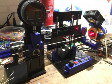
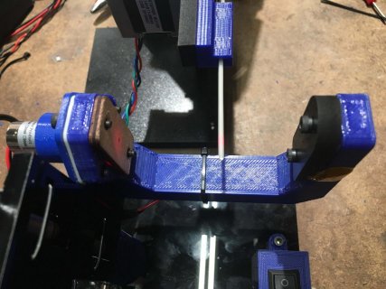
To grip the filament I'm using a toothed, grooved gear from a 3D printer extruder with a stepper. The stepper will keep accurate speed, and using a hard gear rather than a rubber roller insures that the circumference won't change, so the actual pulling speed will be absolutely reliable. The dial indicator measures final diameter, and has a data port which can be interfaced to an arduino or ESP8266 for data logging.

The other thing is the line sweeper I was using for measurement. The last version I made used a threaded rod for linear motion rather than a belt. I made it that large because the idea was to have one beam at the nozzle to measure change in the melted plastic, and another beam at the other end to measure final diameter. I dropped the second beam because the dial indicator is more accurate and doesn't require calibration.

The sweeper works by running the phototransistor into a hardware interrupt pin. When the pin changes, it decides if it is going into or out of shadow, and counts the microseconds between pin changes. Originaly I was using an ATmega32uf (Arduino Pro Micro) for the sweeper, but its high/low threshold is low enough that the the edge trigger was happening during a curve at the bottom of the profile. I found that a 328p (arduino Nano) had a higher threshold, so the trigger happened during the steep drop to darkness, which was a narrower range. Before redesigning the pcb to take a Nano and rebuilding the sweeper, I figured I would give the CCD another look. I think having any moving parts is going to create a threshold of precision that I can't overcome, and the CCD doesn't have any.
 
Nice setup.

The trick here would be a laser line casting a shadow onto the sensor, and some minor shielding or filter to protect against ambient light.

The sensor is very sensitive, so a dark filter like sunglasses use would be useful if you illuminate with a laser, plus block ambient light.

Heh, sidenote, you could use one of the sensors like those found in cheap handheld point-and-measure thermometers to measure the filament exit temperature directly if you found it worthwhile.
A direct optical measurement of the exiting extrusion might be a better overall TEMP PID set point reference than others, who knows?

You could combine 3 laser lines, each at a different angle to the side of the filament, and turn them on one at a time to the same "ccd", to measure "ovality" or roundness.

No matter how you do the linear photodiode array sensor, it is well suited for your task, and I am convinced it will offer superior resolution at both of your measurement points on the filament.
One at the exit of the extruder, and one a little further downstream for final thickness.

I think your current arrangement is very clever for what it is, but yes, having no moving parts is king when it comes to tiny measurements like this.

I intend to get the software working on Teensy/Arduino, and then make a PCB with a socket.

I am thinking you might get away with the 128 pixel model device.
The 256 pixel one is being sunset soon. I don't know what will replace it. They have a range of them, however, so not a crisis.

There are two unique 128 pixel models, and I can't tell what the difference is.

Both are surface mount, crap. AMS is phasing out all the through-hole models, it seems.

You have until may 2017 to buy through-hole models. So maybe surface mount is best anyway to avoid end of life on the part you use.
One I had in mind was TSL1402R, which is one of the models I made a library for. It has through-hole pins.

A reflow plate and stencils, hmmm. Takeaway is there are some decent ones for $100 to $200 out there.
http://www.eevblog.com/forum/chat/hotplate-for-smt-soldering/

Ok the 128 pixel sensors, both 400 pixels per inch.
http://ams.com/eng/Products/Light-Sensors/Linear-Array/TSL1401CL

http://ams.com/eng/Products/Light-Sensors/Linear-Array/TSL1401CCS

Well, back to work. I will try to finish a beta version soon.

In the meantime, I recommend you order a few of those 128 pixel chips, and try the usual Arduino code.

There are a ton of code examples out there for that,

See this, maybe not subpixel, but get something working for now, and we can add subpixel later ... Let me know your actual Arduino module, and I will buy one for testing, Arduino Nano?
Filament Width Sensor with Arduino Pro Micro and TSL1401CL
http://www.thingiverse.com/thing:636420

I found arrow electronics cheaper than Digikey and Mouser, at least for the 1280 pixel chips.
They are likely cheaper for this one as well.
 
Last edited:
Oh, there is also a compatible brand, which claims to be compatible. IC Haus, in Germany makes these same sensors, and at least in some they claim pin compatibility to the ones I am using.

I can't see pin-based ones, there are LGA or BGA surface mount, but these have the 400 pixels per inch at 128 pixels, a bit over 1 cm wide window. What you need ideally.
They also sell a 256 pixel one, if the filament wanders more than a 1cm sensor window width.

iC-LF1401 128x1 Linear Image Sensor with Electronic Shutter Function 128 pixel, 400 pixels per inch
https://www.ichaus.de/product/iC-LF1401

Here is their sensor lineup:
https://www.ichaus.de/keyword/Optical

I am leaning towards the 128 pixel one and the 256 pixel one.
Note the similarity of the part numbers to the TSL1401, TSL1402, made AMS.

LGA or BGA package available
website says, "Pin-to-pin compatible with TSL1401 at higher speed and sensitivity"
https://www.ichaus.de/product/iC-LF1401

only BGA package available
website says, "Function equivalent to TSL1402 (serial mode)"
https://www.ichaus.de/product/iC-LFL1402

Here is their online store for North America.
I think you can buy small quantities here.
http://us-shop.ichaus.com/SearchResults.asp?Cat=22

I will have to research soldering these properly with hobby-grade tools. I am a surface mount newbie, heh.

I just ordered a 5-pack of the iC-LF1401 for testing, it was around $100.00

Note they show Price per Tray: $359.31 (Tray/42 pieces) ($8.56 each), not too pricey.

We'll see if this is a good fit.

But the measurement U frame next to the extruder will need to be much smaller/closer to get a decent shadow I bet.

We'll see. At least this can replace the micrometer with low hassle.

Here's a pic of the sensor being used in a diy pick and place machine:

Laser8B-1024x613.jpg

Picture is from the Lizerd electronics blog:
http://lizerd.se/?page_id=230
 
Last edited:
TSL1410R and TSL1402R availability

Hi folks!

I would like to try the sensors and libraries but the sensors are not available at the usual suspects (Arrow, Digi-key, Mouser). Any hint on where I can buy them? I would like 2 or 3 TSL1410R or TSL1402R. I can not handle SMD/SMT devices.

Thanks.
 
Where to buy

Hi folks!

I would like to try the sensors and libraries but the sensors are not available at the usual suspects (Arrow, Digi-key, Mouser). Any hint on where I can buy them? I would like 2 or 3 TSL1410R or TSL1402R. I can not handle SMD/SMT devices.

Thanks.

Look at my post above for a page where you can order a different brand of sensors, which are compatible to the AMS line, they should work the same Arduino software-wise.


The TSL1402R and some others in that family are marked as end-of-life, production is set to stop soon, and I imagine folks are buying up what remains.

But, not all of the AMS sensors are end of life, and so you can look at Arrow, Mouser, Digikey, Newark, etc for a model still in production.

Here is the whole AMS linear sensor line:
http://ams.com/eng/Products/Light-Sensors/Linear-Array

With the exception of the digital-out model, they are all timed the same, the only number I had to change in Arduino software was the pixel count, (which naturally varies from model to model.)

I'd look for 400 pixels-per-inch models if precision is important for you.

If you can't find an AMS sensor, try the links I posted in this thread above. The sample count minimum you can order through their online store is 5 pieces. For me it was around $100.00 for 5 of the 128 pixel LGA surface mount sensors.

Note these "compatable" sensors come in surface mount LGA and sometimes only BGA surface mount. So, you need a hot air gun and solder paste (as a bare minimum) to solder them to a PCB correctly, but you can find basic hot air guns dirt cheap. A pre-heater hot plate or infrared plate might be a good idea for a more advanced setup. It preheats the board so the hot air gun needs less time to make it flow. I am personally going to try this and we'll see if it is doable. Others use a reflow oven or convert a toaster oven with a PID controller sold for that purpose. I can't say exactly what works and what doesn't, but there is a lot of videos on SMD soldering techniques on You Tube, and it would be good to have a look.
 
Last edited:
Thanks.

I re-checked with Mouser and they will receive some in May. I will have them in back order.
 
At first glance, I am not sure where you would apply it or how.
I looked up SLA 3D printers to refresh my memory.

I see each layer is hardened on the bottom of the tray using a pattern of light to define what gets hardened, and then this hardened layer is peeled off the bottom of the liquid resin tray by briefly moving the tray downwards, while the head holds onto the top of the part.

So I imagine a line sensor camera might be useful for more tightly controlling the motion of the the tray via closed loop, to more precisely return the tray to the same height prior to each exposure?
Also, 3 sensors could be teamed up to level the tray.

Generally speaking, any linear motion limited to within the sensor pixel line length is fair game. Or in the case where you want to return precisely to a reference position.

If that's the thing, also look at inductive sensors as used for home/limit switches, but I think the optical one will be 10 to 100 times more precise, just ballparking it.

In my opinion groomed from machining cnc work, etc, the sensor used for layer position should be at least 10 times higher resolution than the SLA layer thickness.

If an inductive sensor(s) can return the tray to the proper position/leveling with enough repeatability and accuracy, use it, it's much simpler, both mechanically and electronically.

On another idea which might crop up on how to use a line sensor for a SLA 3D printer, I don't think using this for eyeballing the resin level directly with a line scan camera sensor would work well, as the liquid edge would be messy due to old resin stuck to the side of the tray and surface tension optical caustics, etc. I bet tray weight would be a better gauge for determining resin level, perhaps. Tare the empty tray and anything above that is proportional to resin level.

However, that's not to say you couldn't use a line camera sensor to eyeball some other liquid level to compare from a movable tray/ machine base etc.
Say, 3 clear tubes to a common reservoir of colored water or anti-freeze mixed water (whatever carpenter levels use, but dark).
The liquid levels in each tube would stay the same height in the tubes relative to the earth, and the top edge of the liquid could be monitored by the line scan optical sensor as a level reference.
The measured window of the tubes could be two glass slides sealed with a gap where the liquid height top edge is contained,
to prevent optical interference one would get measuring through the tube directly, like microscope slides.
Or, maybe small flat tubing is not so bad to directly measure, gotta experiment. Get a rig set up and play with different ways of sensing, and quantify the accuracy.

Make the liquid dark for high contrast against the air bubble or liquid level in the case of a siphon-like sensor.
In either case, my current software model would detect the bubble position and it's width, relative to the sensor pixels, with sub-pixel accuracy.

Or, to level the tray and re-position it for each exposure, simply have 3 optical line sensors anchored to the frame with adjustable screws, and then the tray tilts and moves relative to them, casting a shadow from an LED by rigging a plate with a slot or a wire in front of the LED for each sensor. Ideally to make this nice, you want an auto-calibrate mode, where you press "calibrate" and it does a little dance and calibrates itself. This infers that there is some artifact present in the machine of known height, size, length, or levelness (water level?), etc for the system to base it's calibration upon.

The are probably much simpler ways to make use of these line scan sensors; I kinda get carried away on some of these ideas.

Bottom line for these optical sensors is, you are either monitoring a shadow or a bright spot, and you get back a digital position relative to the pixels, which can be used for a control loop, such as a PID loop or something similar.
That lets you use the sensor as a super-precise ruler, to put something where you want it.

As for general machine motion closed loop, if you go past a few inches of linear travel to be measured, you are better off with servo motors with encoders, linear encoders for the z axis, or glass scales for the z axis (expensive) etc.
Although, one could use a special code on a DIY transparent film encoder, and eyeball it with a line sensor, to end up with an absolute encoder, but you'd have to work with a printer / photo-lithography shop that specializes in printing a pattern to film at 800 dpi, etc. Or do a simple alternating clear/dark barcode-like pattern, and you have a relative encoder, referenced to a home position.

Or, since you SLA guys like digital projectors... Here's a different twist on positioning... I don't think projected light patterns would be as accurate as the sensor looking at a very close object/shadow, but it precludes the need for physical encoder scales, and what about micro projectors shining a short distance? Maybe that would give you decent precision while still enjoying the benefit of projected light rather than encoder strips.

I always thought this was a cool positioning technique using line sensors:

Lumitrack:Low Cost, High Precision, High SpeedTracking with Projected m-Sequences.

You'd have to study m-codes, non repeating binary patterns, etc:
(I wonder if this paper gave the authors of lumitrack their idea, or vice-versa?)

From AMS, which makes the sensors:

"Position Detection Using Maximal Length Sequences"
http://ams.com/eng/content/view/download/145168

Paper about Lumitrack, from the folks who did it.
https://pdfs.semanticscholar.org/aaf7/344df8199db297711dd1a1d3af54e285caba.pdf

Another path might be, IC-Haus Germany makes some all-in-one encoder/led chips for use in machine control, but I haven't played with them and don't know if they use cheap film or expensive glass encoders, and if they sell encoder strips as well as the chips. US Digital sells a lot of different motion encoders which could be useful.

So, yes, a line camera sensor could be used to return the tray to a precise position, and 3 of them could keep it level as well.
Generally, the machine would wait a moment for the PID closed loop feedback control to stabilize the tray, etc, to the proper position, and then take the next exposure.

The devil is always in the details. If you tell me more about what you seek to control the motion of, and how, then I can focus on ideas around it; right now I am just plopping out some general ideas.
 
Last edited:
Progress on Subpixel code conversion

I am currently coding a new serial protocol for streaming the line sensor data from Teensy to Processing (or other apps in the future)

I am designing it for at least two modes, one which streams the raw pixel data, like it does now, and another mode which streams shadow position and width.

I am doing everything binary, not string characters, to keep data streaming as fast as reasonably possible.

I learned a few new tricks for syncing the stream without colliding the sync byte with other fields or data, and I am bringing this in.
The new raw data stream will support up to 16 bit data, not just 12.

So, once I finish the plumbing for serial, I think copying over the sub-pixel functions will be relatively easy and fast.

Protocols are always the hard part of these things.

Then we will see how fast it can go while doing the sub-pixel code on Teensy 3.6, as well as a version for general Arduino boards.
The main code difference is with Teensy, I use the ADC library which takes advantage of using two seperate ADCs to read an AMS-made sensor which has parallel mode for this purpose,
whereas generally Ardunios do not have this feature. When targeting sensors which do not do parallel mode, like ones from IC-Haus in Germany, then we are serial only and thus use only one ADC anyway, but I still like to use the ADC library for Teensy to provide options to control bit depth or sampling rate, etc. So there will be two code bases I guess, unless there is a way to detect the board when it runs and then decide what code to run. I suppose there is, but I haven't played with that yet.

On to coding...
 
Last edited:
Ian,

I am pretty much done with my new Arduino > Processing serial communication protocol, and now working copying over the sub-pixel code to Teensy 3.6.
The serial is nice enough to release as it's own library or code. I hit all my goals; a more flexible protocol, can send ints and floats for subpixel width and positions, it runs in separate thread on the Processing side, and it 20% faster than using SerialEvent(), and it's ALL binary, not ASCII, except for passing simple debug messages. I will release new Teensy and Processing libraries to github after I use it a little more to find well hidden bugs, etc.

After I move over the sensor sub-pixel code to output the stream of filament-shadow widths, I am wondering how you plan to integrate it; will your motor control run on Teensy 3.x, or Arduino? Separate device or same?
And will I feed my data to your controller over serial, or some other way?

I got thinking...

If you run your motor control AND my sub-pixel code on Teensy 3.5 or 3.6, it would be a lot simpler and faster, running on one fast device rather than two.
That would greatly simplify the control system for your filament extruder if you can run everything on one device without issues (instead of complicating the system with wiring, communication overhead and latency, etc).
And, you still would have the serial stream available to monitor the system with a PC, etc. Processing can export a sketch and itself to a runtime executable too, to have one thing to distribute for serial on a PC.

I know there are some folks using Teensy 3.6 for a cnc controller, so there are some libraries being made for that. And there is talk of using DMA to run the pulses to the motors for greater speed and less CPU involvement.

I am willing to purchase a stepper motor and driver board to experiment towards making it all work together, but I need a direction based on your thoughts on how you'd like to proceed with the general layout, mainly run all on one device or not?

I got the sensors delivered, but they need special soldering gear I don't own yet.

Before I go down that rabbit hole, I want to test with the sensors I already use on a breadboard, and focus funds on a few stepper motors and driver board, etc.

I need to know what motors, controller, and motor drivers you currently are using/familiar with, and then we need to chat and decide on the overall plan.

I am thinking even if a cheaper Arduino can run both my code and your motor control code, it will be a fraction of the speed of Teensy 3.x, so I am leaning towards bringing the whole shebang into Teensy 3.x,
unless there are other reasons against it.

I picture a first test rig scenario, where I adjust a PID loop fed with the width feedback values from different wire gauges, etc, and get it behaving reasonably well around 1.75mm, etc, without actual extrusion involved yet.
Then you can take that code and run it on a real extruder machine with a sensor board and make refinements to the PID settings to perfect it.
I am trying to figure out what I need to set up a meaningful PID loop beta testing rig without complicating it too much.
 
Last edited:
Ian,

I have finished the beta version of the subpixel code on Teensy 3.6. It delivers the shadow width and center position to the serial port at a rapid rate.
I can experiment with putting it on a 16 mhz Arduino too.

The readings from Teensy 3.6 match moment-to-moment with the width and center position calculated in Processing from the same pixel values.

Let me know if you are still interested in using this for a filament width sensor.

I will post code soon, after I clean it up some. But it seems like I got it and it's behaving.
 
I finished a few things lately, and want to let folks know what's about to be released. I will post again when the code is posted.

A serial module for Arduino/Teensy/Processing, which allows binary transfer of sensor data interleaved with other telemetry. Each flavor of transmission is marked in the header, and all flavors of transfer are distributed into separate arrays.
This lets me send a frame of pixel data from an array, and then send some telemetry of say, optical sensor shadow width and position, without interference, maintaining proper separation.
This way I can still see the raw data plot and verify the shadow width and position values calculated & sent from Teensy or Arduino match the ones calculated on the PC in Processing.

The serial framing sync method is improved, with no forbidden data values and thus no bit-shifting to avoid duplicating the sync byte.

The Processing serial end runs in it's own thread and is about 20% faster bit rate than the native Processing serialEvent() method.

New code for reading AMS and IC Haus models linear photodiode arrays, which include configurations with significantly higher sensor frame rates than earlier code, for both Teensy 3.x and regular Arduino.

New code for finding shadow locations and widths with sub-pixel accuracy, for running directly on Teensy 3.x and regular Arduino. (3d filament extruder folks should be happy, now they can measure the width of their filament with good sub-pixel code)
I plan to use this ability in my own prototype instrument for measuring height to workpiece on a cnc machine for sake of workpiece height correction via software.

A new linear photodiode array visualizer Processing sketch update containing many improvements, for viewing the output from linear photodiode array sensors.

It's a lot to chew on, give me a few days to get everything wrapped up and I'll post on my github.
 
Last edited:
cool.

Did you use jssc for serial? I recently used that for bluetooth and USB serial and have had good success. I implemented a sync frame in case of dropped bytes, but your method sounds interesting for sending the occasional other info.
 
I didn't use jssc for serial. Now you got me curious about it, I'll take a look.

I spun a new Java thread that polls for bytes and uses Processing's readBytesUntil().
When it misses a read more than x times, I slow the thread with a millisecond pause to keep it from busy waiting. After the pause it tries again.
The protocol is simple, 3 header bytes and one end marker byte, with data sandwiched in-between.

The first byte is the start marker.

The 2nd byte is the mode, which decides what function to call to unwrap the data and where it ends up.

The 3rd byte is like a leftover, I use it for data lengths up to 252.
Above that I leave it at zero, because it is redundant by way of having the end marker as the main frame sync byte anyway,
however it can be useful to know the decoded length before decoding short data frames.

The data follows, and can be an array or a few int or float values sent as bytes, etc.

Finally, the last byte marks the end of the frame, which again is the sync byte used in readBytesUntil() in Processing.

I don't use serialEvent(), it's slower than my separate thread design by like 20% or more.

All data is encoded with a simple scheme where any byte above 252 is sent as a pair, the first being 253, and the next is 253 - the original value.
On decoding, any byte that = 253 triggers a look at the immediate next byte. The decoded value is found by summing 253 + that 2nd byte.

I don't have a mechanism for sending serial data/commands from Processing to Arduino yet, but I expect to use a non-blocking design,
to prevent glitching the data stream when sending commands to Arduino/Teensy.

Funny thing, on Processing, the bottleneck is not serial framerate, but the drawing framerate.
I get 1500+ serial frames a second from Teensy 3.6 using a 256 pixel sensor.
The same sensor on 16 Mhz Arduino maxes at 100 serial frames per second, heh.

Processing is roaring at 300 frames a second with most draw options turned off, as in a simplified display of one stage of the signal chain.
The good news is we usually don't draw with pixel data, we use it to measure something or as a feedback value, etc.
So drawing is not a big issue, if I want to draw a pile of data and higher abstractions faster there is Open Frameworks.
Point is, serial data frames containing one read of all pixels, arrive much faster then Processing can draw them when using Teensy 3.x.

Heh, your screen name reminded me by the way, I use Linux also, but I am still relatively a newbie compared to hardcore folks, ha.
I do enjoy it and am learning all the time, especially when installing / updating stuff, heh.
 
Last edited:
If you want to look into jssc, here is the relevant code that I put together for grabbing serial data. Ignore a bunch of the variable declarations that aren't pertinent. Make sure to remove any System.out.print calls if you are looking for speed.:

Code:
public class SerialPortManager implements SerialPortEventListener {
	private SerialPort serialPort = null;
	private String sSerialPort = null;
	private boolean bStatus = false, bBinaryMode = false;
	ByteRingBuffer brb = null;
	ByteBuffer testBB = null;
	ByteBuffer sampleBB = null;
	int nSignals = -1, frameVal = -1, nSampleBytes = -1, nSample=0, nSampleRate=0;	
	byte [] frameFragment = new byte[1000];
	
	/**
	 * 
	 * @param sSerialPort
	 */
	public SerialPortManager(String sSerialPort) {
		this.sSerialPort = sSerialPort;
		serialPort = new SerialPort(this.sSerialPort);
		try {
			bStatus = serialPort.openPort();// Open serial port
			System.out.println("open port status: " + bStatus);
			bStatus = serialPort.setParams(38400, 8, 1, 0, false, true);
			serialPort.setFlowControlMode(SerialPort.FLOWCONTROL_NONE);
			serialPort.purgePort(SerialPort.PURGE_RXCLEAR);
//			brb = new ByteRingBuffer(1000000);
			brb = new ByteRingBuffer(65536);
			serialPort.addEventListener(this, SerialPort.MASK_RXCHAR);
		} catch (SerialPortException e) {System.out.println("serialPort init ex: " + e);}
		System.out.println("set params status: " + bStatus);
	}
	
    @Override
    public void serialEvent(SerialPortEvent p_oEvent) {
        byte[] rxBytes = null;
        
        switch(p_oEvent.getEventType()) {
            case SerialPortEvent.RXCHAR:
                try {
                    rxBytes = serialPort.readBytes();
                } catch(Exception e) {e.printStackTrace();}
                brb.write(rxBytes);
                break;
            default:
                break;
        }
    }

}
 
Status
Not open for further replies.
Back
Top