New library and example: Read-TSL1410R-Optical-Sensor-using-Teensy-3.x

Status
Not open for further replies.

Mr Mayhem

Well-known member
I published a new class library on Github for reading the AMS TSL1410R linear photodiode array,
and sending the sensor pixel data over USB serial to a Processing visualization sketch.
https://github.com/Mr-Mayhem/Read-TSL1410R-Optical-Sensor-using-Teensy-3.x

It is complete with Arduino and Processing sketch examples.

This is similiar to the TSL1402R for which I posted a similiar software earlier,
but this sensor has 1280 pixels, instead of 256.
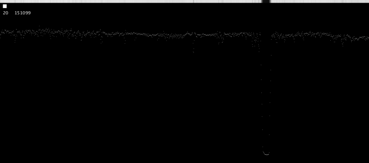
Processing_Screen_Capture-001500.png


The notch in the plot is a small allen key tool resting on the sensor window, casting a shadow from a white LED desk lamp overhead.

It has a 5 times slower framerate than the TSL1402R.

This sensor would be a good candidate if you need more
absolute sensor length, perhaps for a spectrometer project.
The native resolution is 400 pixels per inch, same as the TSL1402R.

The SI pin from Teensy 3.x are wired to pins 2, 3, 8, and 9 on the TSL1410R sensor which is SI1 and SI2 and HOLD1 and HOLD2, respectively.
The clock pin from Teensy 3.x goes to pins 4 and 10 on the TSL1410R senor. Forget one and see one half of the data missing in the plot.

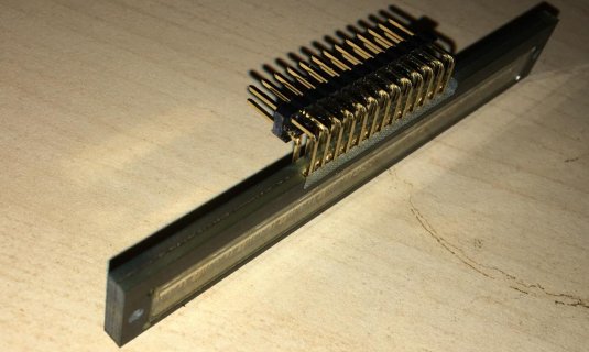
I had to expand the holes to fit wires or pins through the connector holes,
because they come too small.

I used 2 PCB drills, a 0.7mm drill, followed by 1.0mm, to expand the holes by twisting
the drill bit with my fingers, using the original holes as a pilot hole.
Such tiny bits are easy to break, be careful. I broke more than one,
but I finished just fine using the broken stub.

I soldered short wires on my first one.
I will use standard 0.1" pin headers on the next one.
They are for sale in the pjrc.com online store.

Sensor hole Pitch is 0.1" standard breadboard spacing.

I hook-shaped the wires with needle nose pliers,
ans stuck them through the expanded holes.

Next I crimped the wires a little so they made a slight grip to the pad,
and soldered them on the optical window side of the sensor.

The longer part of the wires comes out the rear (non window side).
Then I soldered the rear pads as well.

I trimmed the wires to the same length, and bent them at 90 degrees over the edge of
a table, so that the sensor faces up when the wires are inserted into the breadboard.

Finally the wired sensor is stuck into a row of adjacent holes in the breadboard.

I made minor changes to the TSL1402R library and the demos to accommodate the
higher pixel count.

I am here to help if anyone wants to try using this sensor with my library.

I am working on sub-pixel resolution edge detection for locating shadows and lasers more accurately than the pixel pitch.
 
Last edited:
Wow, that was fast! Gonna pull the trigger and order this. I'll try and find a solution without drilling holes. I think maybe some stiff copper wire, or find smaller headers, or shave down each header to fit.

edit: Went ahead and ordered 2 of them. Like you said, they were considerably cheaper at arrow electronics.
 
Last edited:
Great idea! Your soldering craftsmanship looks great too. My first one with wires looks like a hatchet job by comparison, ha!

I think the top and bottom pads of any given hole are the same electrically, so in that sense you don't need two rows of pins,
but I see it increases rigidity a lot.
 
Great idea! Your soldering craftsmanship looks great too. My first one with wires looks like a hatchet job by comparison, ha!

I think the top and bottom pads of any given hole are the same electrically, so in that sense you don't need two rows of pins,
but I see it increases rigidity a lot.

It's not soldered yet. I'll do that this weekend, and we'll see how it fairs.
 
Well, great mounting job, hah. I was kinda wondering about that after I posted, but a proper and neat pre-solder fit, nonetheless.

I am making progress on the edge finding algorithms. I am taking the longer tour of teaching myself the steps of optical edge finding, using visualization experiments in Processing, instead of the the usual practice of merely pasting some code from the internet and tweaking it. It's kinda hard to do useful improvements to such algorithms without being somewhat familiar with how they work.

My pile of experiments (Processing sketches) and some basic notes is here:

https://github.com/Mr-Mayhem/DSP_Snippets_For_Processing

A work in progress. The example sketches are commented fairly densely as well.

My next step is to bring some of these DSP elements together in a class, to form a data-processing pipeline which detects edges.

After that, I will learn more about the stunt of fitting a parabola (quadratic polynomial interpolation, whew, big words) to the top of the "edge peaks" created from convolution, and finally be able to understand what the existing sub-pixel code (from the filament width sensor projects) is doing, and improve upon it as needed.

I think that existing code skipped the convolution step, and went right to finding the 2 peaks in the slope of the original sensor data (where the shadow's 'notch' sides are in the plot)
and then fitting a parabola to each of those peaks to obtain sub-pixel width. My mod subtracts the difference of these to obtain the sub-pixel center of the shadow.

It occurred to me that my 2 Processing sketches for plotting data from the 2 sensors have all the existing sub-pixel code commented out because I found it slowed down the frame rate quite a bit, and tiny shadow sub-pixel changes were too jumpy. So all this talk and no show may be a bit annoying to some. But its coming.

Sometimes the subpixel value went the wrong direction in a cyclic error as the shadow was very slowly moved across the sensor. I may have implemented it incorrectly too, which is another reason why I am studying how this algorithms works.

I found another spin-off of the filament width code, "Zabe Filiment Width Sensor" to compare as well, which looks like someone comprehensively re-built that subpixel code to make it more understandable and perhaps work better:

https://www.thingiverse.com/thing:668377
Incidentally, this project uses a TSL1402R sensor, the one we discussed in this thread.

The quadratic 'parabola fitting" sub-pixel method works best with low-noise input, and performs worse fast as noise creeps up. I suspect the current input to it is too course and noisy. I will post a new version shortly, after I make it behave better, perhaps by doing a few pre-processing steps prior to the parabola fitting step. Always a speed trade-off, but I will make each step able to turn on or off by command, so folks can tailor it to their needs.
 
Last edited:
I'm trying to wire it up, but I only have a Teensy 3.2. What do you suggest for these pins?

T3.6 = T3.2
CLKPin 24 = 2? (assume it doesn't matter much)
SI Pin 25 = 3? (assume it doesn't matter much)
Apin1 14 = 16? (can be accessed by both ADCs)
Apin2 39 = 17? (can be accessed by both ADCs)
 
I've wired it as such:

CLKPin = 2 -> Pin 4,10
SI Pin = 3 -> Pin 2,3,8,9
Apin1 = 16 -> 6
Apin2 = 17 -> 12
GND = GND -> GND
Pwr = 3.3V -> VDD

This is working! Looks great, but I only get 1/2 the array coming through. The left side somes thru, but the right side does not.
Any ideas? Is there another ADC pin that I need to use? Time to get a T3.6? I'm not opposed to that. :)
 
nvm, it works completely. I forgot I had a teensy 3.6 and tried on that but had the same problem. So, double-checking it, I had the HOLD1 mis-wired. After that it worked on T3.6, so I switched it back to T3.2 & it works on that too with the same pin assignments that I posted above. Nice work!

BTW, it's much easier to solder with those right-angle headers from the bottom. If I was to do it again I'd probably just do it from the bottom, and possibly flow some solder from the top thru the hole to give it even more anchoring. As I did it I don't like putting 2 rows of headers into the breadboard, as it's too hard to pull out. I could just cut the bottom portion of the top right-angle header so the 2nd row doesn't plug into the breadboard.
 
I see, a double row is header is difficult to plug in to the breadboard. So you are saying, one row is better overall, at least where it plugs into the breadboard. Also, it's easier if one solders the headers to the back side of the sensor first. I got some straight headers, but maybe I want to use right angle ones. I haven't cad-modeled my sensor housing yet, so the question of which style of headers to use on my 2nd big sensor is still up in the air for me.

Yesterday I improved the serial port code on the Processing sketch for both sensors, so it does not lag behind in the beginning. So if you haven't, give the new Processing sketch a try. I added optional interpolation too, but it needs further work, specifically to window or limit the data before other steps, so the extra features work only upon data where the shadow falls, not the whole sensor frame. The code is now identical in the Processing sketches, except for SENSOR_PIXELS being 256 and 1280 respectively.

I am currently working on adding nice edge detection code. When it's done, it will do windowing to limit processing to the shadow area, then convolution, then interpolation, then parabola fitting the top 3 points of the peaks for sub-pixel res. I might move interpolation prior to convolution because I am a bit uncertain where it is best applied.

I also plan to update the Arduino code so can do edge detection as well.

After that, I plan to build a data visualizer using Open Frameworks, which should improve performance a lot.

Way down the road, we might investigate using 3 led light sources at 3 angles and averaging 3 separate exposures, which makes possible another sub-pixel averaging method. This is used in the 3 LED filament width sensor, but i don't know if the angles they chose were optimal to get 1/2 pixel overlay. I suspect they missed that subtle detail of the ideal angle = 1/2 pixel shadow shift, and just chose a wide angle. Half-pixel offset would imply the 3 leds would be very close together.

I intend to rig up a micrometer to a moving stage & shadow-casting wire, and measure accuracy, calibrate, compare edge finding methods, etc. But, I want to make the edge-finding code reasonably well-behaved first.

The last thing I can imagine would be to add a laser mode, which would be optimized for finding the center of a laser line crossing the sensor.
 
Last edited:
On the Processing example sketches for the linear sensors, I added a threshold to limit interpolation to occur only below a certain brightness, so it ends up only interpolating significant shadows. This way we are not wasting resources working on uninteresting data. Soon I will add hysteresis, so it doesn't trigger multiple times.
 
I see, a double row is header is difficult to plug in to the breadboard. So you are saying, one row is better overall, at least where it plugs into the breadboard. Also, it's easier if one solders the headers to the back side of the sensor first. I got some straight headers, but maybe I want to use right angle ones. I haven't cad-modeled my sensor housing yet, so the question of which style of headers to use on my 2nd big sensor is still up in the air for me.

I think the right-angle header is much easier to solder to the bottom pads. With 13 of of them, it seems like it would be pretty secure with only the bottom ones. Could probably cut the length of the portion that is soldered to the underpads in 1/2, so that it minimizes the leverage placed on the solder joints when inserting/removing from breadboard. You only need a horizontal portion that is the length of the underpad.

I wonder if collimating (making parallel) the light would help in your detection.

You did a nice job of syncing the frames in processing. I was surprised to see it re-sync even when I was plugging/unplugging wires while it was running.
 
I see, so the minimum length used for the under pads will minimize the leverage placed upon them during breadboard insertion/removal. I have my sensor facing up towards a desk-clamp magnifier lamp which features a large circle of white LEDs. Both the topics in your previous post connect to this. On the topic of headers, the right angle works nice for making the sensor face the lamp. So, yes, still gotta order some for the next sensor if it's going to be facing up, and I will heed your advice on how to do that.

On the topic of making the light parallel, yes, there may be something to that. I need to try a single LED light source, it worked pretty well for doing casual spectrometer setup through a diffraction grating card to a camera. Haven't tried that with the linear sensor yet, but will in time.

I was also thinking about a bunch of other things, like lenses to collimate the light, laser light source, spread and then collimated, 3 LEDs, each at an angle to play with half-pixel shifting on ether side of center, etc. That last one might effectively double the sensor's resolution, even prior to normal sub-pixel processing. The simple obvious solution is to use a single LED, instead of a large LED ring on my decklamp. I got so used to using it that I overlooked this issue, heh. But to answer your suggestion, yes, I will try more collimated light source, good idea.

I am up to my eyeballs now working on understanding convolution, filtering, various sup-pixel techniques, and setting up sketches to evaluate and compare sub-pixel methods in a quasi-objective manner. I want to simulate the sensor data so I can virtually move the shadow fractions of a pixel in code, then see how the various sub-pixel techniques perform while measuring the error from the known simulated edge location. I will take your advice and see what happens with a sharper pin-point light source, so the shadows get sharper, and use that image snapshot of data for testing. I also wondered about de-collimating the light, so the shadow is more gaussian, like the bottom of the shadow plot shape would appear curved not flat. I will try both in time.

On the processing code, which one are you using? I suppose the newer one, which uses BufferUntil() and serialEvent() ? That was the most elegant solution I have found so far. I think bufferuntil means that it quits buffering after finding the interesting byte, and then waits for the serialEvent to finish. In the meantime, while drawing the screen, I think it allows other frames to pass by ignored, so it has the luxury of ignoring them until it is ready, rather than accumulating each and every byte that comes down the wire?

I would have to look at the Processing serial library source to know for sure, but that is the code that probably deserves the credit for restoring after being unplugged. Also windows is terrible at such unplugging and hides this benefit on my test laptop, so thanks for pointing it out. Linux is much better for unplugging/reconnecting the usb serial, I read somewhere. Thanks for the complement.

One trick to speed using serial port bufferuntil() in conjunction with serialEvent():
I suspect it helps the frame rate to set the framerate() high, even though this seems counter-intuitive.

I will keep updating my little Processing collection until I have some decent sub-pixel code that I can comprehend.
 
Last edited:
I just published a new, improved visualizer for linear photodiode array sensors.

"Linear_Array_Sensor_Subpixel_Visualizer.pde, a demo of subpixel resolution shadow position measurement and visualization,
using a TSL1402R or TSL1410R linear photodiode array via serial port, or synthesized waveforms."

see https://github.com/Mr-Mayhem/DSP_Snippets_For_Processing
and click on "Linear_Array_Sensor_Subpixel_Visualizer.pde" to see source code

This time I think I nailed the sub pixel resolution feature.
It reports the width and center position of a single shadow falling upon the face of the sensor with sub pixel precision.
The sensor pixels are 63.5 microns apart and I am seeing the noise floor at the micron level. I can measure 10 microns fairly reliably, and 100 microns no problem. For the unfamiliar, 1000 microns is 1 millimeter. This is with the Teensy 3.6 ADC library set to maximum speed and no averaging while reading the sensor analog values.

Plus the cool part is, I unveiled the inner workings with graphics, so you can appreciate the beauty of this quadratic interpolation subpixel algorithm as you shift the shadow around slowly. This algorithm can be used to improve many other kinds of sensors where peaks and troughs need to be located precisely.

Essentially, it smooths the data via convolution with a Gaussian bell curve, finds the 1st derivatives, and fits parabolas to the positive and negative peaks within that 1st derivative data to solve for the sub-pixel position. (That all-important value to the right of the decimal point.)

I will be working on better screen scaling so you can zoom in and scroll anywhere in the data, auto-calibration using dowel pins or drill bits, and moving this into the Arduino library I wrote which feeds this visualizer from Teensy 3.6. Then the Arduino side can send positions instead of raw data, which should be a faster frame rate. Or it can send a window containing only the interesting data in the neighborhood of the shadow, so it can get by with sending fewer bytes, which would also speed up the frame rate.

The sketch also runs in standalone mode, using some built in waveforms. Select the data source and off you go.
It is compatible with my Teensy library for TSL1402R or TSL1410R sensors. Just set SENSOR_PIXELS for whichever sensor you are using.

Below are the Arduino sketches for Teensy 3.6 which feed this new Processing visualizer. They haven't changed much since I published them, but soon will be updated with the new features mentioned above.

https://github.com/Mr-Mayhem/Read-TSL1402R-Optical-Sensor-using-Teensy-3.x

https://github.com/Mr-Mayhem/Read-TSL1410R-Optical-Sensor-using-Teensy-3.x

I will plop a screen shot or video soon.
 
Last edited:
I just posted an update to my visualizer sketch. It takes the usb serial data from my linear photodiode array libraries for TSL1402R or TSL1410R sensors, (which run on Teensy 3.6 nicely) and displays the position and width of a shadow falling on the sensor. It now features pan & zoom of the data display, and the code is more properly broken down into classes. I moved it from it's old location under "Processing Snippets", to it's own repository:

https://github.com/Mr-Mayhem/Linear_Array_Sensor_Subpixel_Visualizer

Still working on additional features.
 
I posted an update to the TSL1410R.cpp file. A loop that was supposed to count up to 1280 was only set to count to 1080. So that is now fixed, and the changes are merged.
 
My fancy Processing sketch for the TSL1410R and TSL1402R has been updated to include:

Tracking the position of multiple shadows falling upon the sensor and collecting them into an array as well as showing them on the screen

Added a basic waterfall history display for shadow positions.

Pan and zoom the data plot

Dynamically adjust the gaussian smoothing kernel sigma with the mouse wheel.

Lots of speed improvements and tweaks. It's pretty nice looking too.

This could be used for many kinds of position or tracking applications.

I will continue over the next few months to make improvements and add more features as I ready to use it for a cnc sensor system I am building.

In the final version, I want to generate a point cloud of a workpiece mounted on a cnc machine and use it for height correction.
This will go much faster than the method of using a mechanical probe to gather the points one at a time.

See this at

https://github.com/Mr-Mayhem/Linear_Array_Sensor_Subpixel_Visualizer
 
Last edited:
I've been looking at this for a filament sensor, for extrusion. I would like to mount a sensor on the nozzle of an extruder to measure changes in size of the melted plastic as it stretches, as an input for PID control of the motor doing the pulling. I would ideally be able to detect changes within 5-10 microns. The filament wouldn't be able to touch the sensor since it is melted, it would be a couple mm away. That at least creates a larger shadow edge which gives more pixels to work with. Also several measurements per second is plenty, which leaves room for plenty of averaging.

Do you think it could track changes in the range of .005-.01mm?
Does the size and diffuseness(?) of the edge affect the stability of the sub pixel reading?
Have you begun to port the sub pixel code to the Arduino? Ultimately I will need the library to output a number that I can feed to the PID routine.

Let me answer each of your questions in turn...

"The filament wouldn't be able to touch the sensor since it is melted, it would be a couple mm away."

In general that's fine. See the description of keeping the light rays collimated (parallel as possible) below.

In your planned filament sensor design, is the shadow cast upon the sensor window from a softened filament?
So, it seems you want to stretch a softened filament to a particular thickness using PID control, prior to extrusion?
I think I understand. Preheat the filament, and stretch it to a specified thickness, and then that section goes on it's merry way to final extrusion.
Repeat like an inchworm movement perhaps? Or more likely the pull is constant, but the braking friction varies with PID control, or vice-versa kind of thing.
In any case there is a difference in tension of the softened filament so the stretching varies, which the sensor sees and provides feedback, ok.

"Have you begun to port the sub pixel code to the Arduino?"

No, not yet. I am about to begin, though. For one shadow it's pretty much understood what needs to happen in the code functionality.
Up to now I focused upon making it work with multiple shadows as well as only one shadow.
Perhaps this would be useful in your application to use multiple filaments passing over the sensor chip window at the same time,
perhaps different colored filaments, different thicknesses, different materials, etc.

So, I guess it's time to translate the Processing subpixel code to run on Teensy Arduino, and regular Arduino.
Ok, well I will now focus on this goal then; I appreciate your interest and wish to be helpful in getting it right.

Note when you mention Arduino, I wrote this for Teensy, and have not back-engineered it to work on original 16 mhz Arduinos, not that it won't, but that I did not try this yet.
Maybe by Ardunio, you mean Teensy running Teensyduino. Fine then. Otherwise, it's one more port away; I will translate it to Teensy 3.6, then regular 16 mhz Arduino.

One nice benefit of using Teensy 3.6 and the ADC library for Teensy, I take advantage of the simultaneous dual ADC read feature;
I can read both analog output pins of the sensor together at the same instant.

With a normal Arduino this is not possible, so the parallel reading of the sensor morphs into the act of reading from one sensor analog output pin, then the other pin in quick succession,
which causes minor center pixel and last pixel dips in the pixel values, when using parallel mode of the sensor. (As compared to reading both analog pins at the same instant.)

For 16 mhz Arduino, as you are not expecting to require so much speed, there still remains the possibility of using the serial mode of the sensor,
where the analog values are clocked out from only one pin of the sensor to one ADC sequentially.
It would run half as fast as parallel mode, and require only one Arduino ADC to read it.
The wiring for serial mode of the sensor is different, but not difficult to figure out using the sensor data sheet.

Disregard this serial reading method if you intend to use Teensy with dual ADC. It does parallel and reads the pins at the same instant. Have your cake and eat it too kind of solution.

But also note, artifacts caused by this not-simultaneous read timing are fairly minor in parallel mode of the sensor,
yet completely avoidable with Teensy 3.5, 3.6 and the dual ADC feature, or using serial mode.

Faster than a few samples per second should be achievable, but it's better to go as fast as one can, because you want some wiggle room for crisp PID performance.
I think this is achievable, but let's wait and see how fast it goes on the Teensy 3.6 and later the normal 16 mhz Arduino.

You also asked about how the shadows are affected by distance, etc. The answer is the light should be as collimated as possible, so the rays are parallel as possible.
This means the LED light should come through a narrow slit, or maybe an expanded and collimated "wider diameter than normal" laser beam in the ideal optical setup.
The distance from the light to the sensor should be long enough to make the light appear more point-like from the perspective of the sensor.
This explains the use of tube-like light paths in many designs. You want sharp shadows, so a tiny yet very bright point of light far away is ideal, yes?
In this ideal case, the shadow width would change little from the filament to the sensor, because the light source rays are very parallel.

In less ideal path lengths, the problem settles out in calibration anyway, so long as the distance from the sensor to the filament does not change appreciably.
That variable boils down to the design. Assuming a round filament stretched across a bridge of sorts under tension, I would bet it would not contribute significant error.
If the filament is ridged or square, etc, you will see ripple in the thickness as it twists, so maybe multiple light angles with unique exposure times, then averaged,
makes sense to cancel that species of error out.

Also remember, the light brightness affects required exposure time, just like normal cameras, so to speed up use a bright light source; either a point-like super-bright white LED through a slit, or widened and re-collimated laser.

Some other filament width sensors.
They seem to differ from your proposal by just reading thickness of the filament and using it to speed or slow the extruder feed rate,
not for the controlled stretching of a softened filament. Is that right?

Example 1, Filament width sensor by Flipper version 3
http://www.thingiverse.com/thing:454584

Example 2, Zabe Filiament width sensor
http://www.thingiverse.com/thing:668377

Example 3, uses 3 different angles of led light projection
http://www.wamungo.co.uk/PrintModel...th-Arduino-Pro-Micro-54f55b5089702a0f788842b8

You wrote:
"Do you think it could track changes in the range of .005-.01mm? "

Yes. I see noise-free stable readings in microns, and sometimes better if I let vibrations settle out, just from an led projecting from it's hung position
a few feet above the sensor, not even using a slit to narrow it.
So I think it's a safe bet to get repeatable accuracy at 0.005 to 0.01 mm in the shadow width.

I will post here when I get it translated.

If you can, please explain a little more on the concept and how it works in context of the entire 3d printer system,
the advantages of your proposed method and how it differs from existing filament width feedback systems seen in the wild.

I will begin tonight to translate the sub pixel code.

I will set it up to have at least 2 modes, raw data streaming like it is now, and shadow(s) width/position values streaming.
 
Last edited:
The extruder pushes the plastic out an opening in the nozzle that is perhaps 2.5mm. A motorized puller pulls it, causing it to stretch as it cools until it reaches its final diameter around 1.75. Faster pulling means more stretching and a smaller diameter. The rate of extrusion tends to vary, so if extrusion speeds up, the plastic at the nozzle will begin to thicken and the puller must speed up to compensate. If extrusion slows, the plastic will shrink because the puller is now too fast, and must slow down.

The filament measuring devices on Thingiverse are meant to measure the final diameter, and depend on the filament pressing on the CCD. This means they must be far enough from the nozzle for the filament to be fully cooled, which means the feedback loop for the PID is fairly large. For measuring final filament diameter, it is easy enough to set up a dial indicator with a roller. I would like to attach the optical measurement device to the nozzle and measure changes in diameter as close to the opening as possible. Calibrating the reading to mm isn't really important, the only thing I am interested is in change. I would like the PID to maintain diameter within .02-.01mm, so the closer it gets to micron precision, the better the PID will be able to react to trends within that range.

For a point source, I've been using a laser pointer shining through a pinhole that is smaller than the filament. Since the device will be attached to the nozzle, there is no way for the distance between the plastic and sensor to change so it isn't as important for the light to be well collimated.

I had been experimenting with a measurement device based on laser micrometers which sweep a line across the measurement area. Rather than use a spinning mirror and lenses, I had the laser shining into a phototransistor, and swept the pair up and down past the filament. The measurement is determined by the amount of time the sensor is in shadow. The laser was behind a .3mm pinhole, as was the sensor, to keep the shadow as sharp as possible. The phototransistor was plugged in to digital pins with hardware interrupts, with the trigger point occuring somewhere along the steep part of the transition. Unlike a CCD, this method has the advantage of practically unlimited resolution, but because there is more complexity it is harder to maintain consistency. I couldn't get precision below .01 without slowing it down too much to be practical for running the PID. A CCD is much simpler since there aren't moving parts, but it is much more dependent on subpixel edge detection, which I don't have the knowledge to develop on my own. I'll try out the versions on Thingiverse, but I'm encouraged by the extra work you have put into it.

I developed and sell the Filawinder, a filament spooler made to go along with the Filastruder, and I would like to create a closed loop puller system to go along with them. Basing it on the Teensy would make it much more expensive than a 16bit AVR, though it might be worth it if I can keep other costs down. Running it on something like a NodeMCU would be cool, using the integrated Wifi for visualization and logging over the network.

I'm also interested in your CNC application. I recently got a Shapeoko, and would like to try milling PCBs at some point. Until now I have been using a laser cutter to burn off spray paint resist before etching, and still have to use a drill press for the holes.
 
I saw a video of Lyman filament extruder, which is listed around a grand, I assume this is the general species of machine we are discussing?


There is a lot more where that came from:
https://www.youtube.com/results?search_query=filament+extruder

It appears that you are trying to do the same kind of thing, but at a lower price point, yet maintaining reasonable filament consistency.
It translates into having to pull more rabbits out of your engineering hat to maintain par. But that's what makes it fun and worthwhile.

On the workings as I now understand them:
Plastic bits are placed into the intake hopper and pressed into a heated chamber. Not unlike the extruder found in plastic injection molding machines,
the melted plastic is forced out through a heated, round extrusion nozzle via a motorized screw pump. The hot extruded plastic exits the nozzle as a filament,
which is pulled slightly by a take-up wheel.
The new plastic filament cools before it makes contact with the pulling wheel, and is wound on a spool for later use in 3d printers.

Let me say nice idea; filament is kinda pricey and that cost adds up. Where does one source the plastic? Can you recycle it too?

I can see the challenge of maintaining even thickness. I will have to look at the common methods to see the range of options used within the field.

Soon I will research how others met the question of maintaining even thickness.

But for now, I will focus below on the measurement possibilities.

As a baseline estimate, you want the take-up wheel to rotate in almost-fixed proportion to the natural speed of the extrusion exiting the nozzle, which itself is related to extrusion screw turns.
Any slippage in the ratio will need the PID loop you speak of to correct errors in that baseline assumption.
So, you want the take-up wheel to adjust it's speed by comparing the sensor values of filament thickness, to a set-point thickness value, using a classic PID feedback control scheme.

You can measure thickness with the sensor, but you can also measure the catenary droop of the tensioned soft filament.
One possible advantage of measuring droop, is that it varies more mm than the thickness would, and thus would have the effect of amplifying the measurement in absolute sensor pixels,
at least when the pulling wheel is far enough away from the extruder nozzle so the dip changes are substantial.
A slight difference in speed would make a large difference in how far the suspended filament dips.

You could put the sensor in the center between the extruder and the first wheel, with the pixel strip arranged vertically and the light projecting onto the sensor from the side,
casting the filament's shadow.
The set point would correspond to absolute shadow position, which corresponds to a preferred amount of dip.
If this worked to your satisfaction, you could have multiple filaments at different heights passing at the same time and independently controlled, leveraging the same sensor.
There are two sensors in the series which have like a 3+ inches long pixel strip, plenty of room, ha. But I drift...

I can see the advantage of measuring the thickness right after the nozzle. The feedback loop would operate faster, so the control would be tighter, one would expect.
But I wonder, if we fixate on thickness, is it possible to see filament spilling on the floor even if a thickness is maintained? At least for thicker thicknesses?
And if the thickness is set low, then couldn't the result be the filament is stretched past the breaking point? Maybe these extremes can be avoided by constraining the range of
thicknesses chosen as set point.
On the other hand, a droop measurement strategy would more directly avoid this problem because it is essentially measuring slack itself.

After watching the Lyman video above, I am wondering how he is doing it. He suggests in the text overlay at time 2:50 that the take up wheel is synced to the extruder screw.
Does that mean he set a fixed ratio between those two motors, and doesn't use a PID?
But at time 4:50 he mentions a PID as one of the items mounted in the console. Hmmm.

Maybe he has a more consistent screw pump, which does not vary the extrusion rate considerably?
I need to look again.

I have played with Arduino running on ESP8266, with the sensor, but it's ADC is crappy because it gets shared for an internal WiFi gain control, which interrupts the readings periodically.
I will be having a look at the ESP32, which promises to be better all around. For WiFi or bluetooth, I would use that module, it's a no-brainer after the codebase matures some.
But Teensy can also do fast USB serial and Ethernet, and PID loops require low latency and low jitter data paths in general, something to think about. CNC machine PIDs are really touchy
in this respect, but a much faster animal than the speeds we are worried about here.

I started porting the code so we will have something to work with soon.

On the CNC application, it essentially is using the linear photodiode array sensor to measure surface warp, etc, in order to correct for it in software.
I have not begun the mechanical design, I am still weighing my options. I could do optical only, or a probe, or a line laser looking from the side at artifacts placed
on the workpiece (in case of a pcb or flat item), I am kinda lost in choosing because I want to make it novel to some extent.

But I am open to suggestions. Also, these sensors would be great for 3d printer auto-bed leveling feedback. With sub pixel code they are more than accurate enough.

If you know more examples of how others solved this challenge of even extrusion, please share them. Maybe more expensive options could be hobby-engineered into plausibility.

I will do a dig and see what methods are common at different price points and levels of sophistication.
 
Last edited:
I see the Noztek one looks very professional, but their extruder is priced way higher than yours, at 894 pounds sterling.
And the winder is sold separately I believe for 595 pounds. Convert to dollars, add international shipping, pricey.
But a nice looking system.

Here is their winder video:

They use a laser sensor looking at the catenary droop in the hanging filament apparently, like I suggested above I suspect.

A linear photodiode array would be better than a few separate photo diodes, like theirs appears to be.
A linear photodiode array provides good range of travel, more resolution, more consistency of distance between pixels, etc.
So there is still advantage to employing linear photodiode array for keeping the slack constant.

Noztek mentions in their extrusion machine manual that the extrusion head temperature directly affects filament diameter.

Higher temp = thinner, lower temp = thicker.

Maybe the take up wheel should not be used to control the thickness if temperature plays such a dominant role?

Maybe instead you mean control the temperature of the head by monitoring the thickness with the photodiode array? That seems to make more sense.

Following this trend of thought, do you have a thermistor in your extruder head? Is your temperature control closed loop?
Is the closed loop bang-bang control like a thermostat, or is it PID control?

Maybe the PID mentioned in the Lyman video in my previous post is for temp control, not for controlling filament pull or winder speed.

One probably needs one PID for extruder temperature control, and another separate one for control of the spooler rotation speed by monitoring the droop in the slack.

My inclination would be to get the temp very precisely controlled in PID closed loop.
Then have the take-up wheel not tug on the filament, but simply keep pace with the extrusion, resulting in constant slack or droop, like the example sensor in the video above.

I know precise temp control is difficult with so many variables, like how increased feed rate cools the head more, thermal propagation lag to the thermistor, etc.

Please clarify if you intend to control the filament diameter by changing the temperature, or by changing the pull on the line. Maybe we simply confused these two things.

At any rate, you still need a way to maintain a constant feed rate on the spooler, even if thickness is not controlled there.

It makes sense to me to have one photodiode array sensor monitoring thickness right at the extruder nozzle exit and controlling temperature,
and another photodiode array monitoring the droop in the slack to the winder, located at the lowest point of the filament catenary or drooping curve, and controlling the winder take-up speed.

I suspect there is no reason that a regular 16mhz Arduino could not handle this task, because like you said earlier, you really only need to poll it a few times per second, not dozens or hundreds.

I am working now to translate the subpixel code and I see this as a very good application for it.
 
Last edited:
Here is a video of the Filastruder and Filawinder https://www.youtube.com/watch?v=VXkRJwKwohw also a time lapse of a prototype https://youtu.be/TbsIDJNjq2M?t=50s

The Filastruder is mounted vertically, the filament extrudes down into a loop and back up to the winder. At the bottom of the loop is a line of 4 photoresistors, with a line following function tracking the location of the filament. The spool speeds up and slows down as needed to keep the filament in place. With a puller, the filament is constrained. If extrusion speeds up but the puller does not, there is nowhere for the extra plastic to go so it bunches up, increasing the thickness. With the vertical setup, gravity is pulling the filament. Unlike the puller, there is nothing constraining the filament so if it speeds up, the only result is the loop gets lower. As long as the length (and weight) of the loop is maintained and the temperature (therefore viscosity) is constant, the stretching force stays the same. As long as the loop is U shaped, any pulling from the spool is isolated from the nozzle and cannot act to stretch it. Only gravity (which is constant) can stretch it.

The downside is that the equipment must be mounted to a wall or a board. It takes a long time to guide the filament from the extruder to the winder for initial setup, and it can take a long time to smooth out wobble that resulted from the handling. With a puller, everything can be lined up on a desktop, and there is more direct control of the filament diameter. With the falling loop, diameter is determined by nozzle opening and temperature. The dropping loop doesn't work inline on a desktop because the filament is rigid. If it is supported at each end over a couple of feet, it won't droop. It also twists due to the turning of the screw, so it is as likely to go sideways as down. With the vertical setup the loop is large enough that the weight of the hanging filament is enough to counter its tendency to twist.

Pulling the filament straight with the puller is more convenient, but harder to sync. With a desktop extruder, the flights of the screw are small in relation to the pellets so variation in the number of pellets picked up by each turn of the screw has more effect on the amount of plastic pushed into the melt zone with each turn. That leads to the variation in the pressure in the melt zone, and changes in speed of the plastic coming out of the nozzle.

The Filastruder is $300, and the Filawinder to $170. I feel like a measurement/puller kit that can be added in to the system should ideally fall in the $150-$200 range. Part of the reason to make your own filament is cost, so it doesn't make a lot of sense if it is going to be pushing $1000. Ideally the price of a thing should be 2.5x the materials, so it adds up quick.
 
The Noztek winder is actually my Filawinder. I made the design open source with no commercial restriction, so they were free to make their own version. They chose to go with a prettier, but more expensive powder-coated sheet metal construction.

The temperature is controlled by a thermocouple inside the nozzle, which feeds an off-the-shelf PID control unit which does a good job of maintaining the temp. The four sensors do a good job tracking the loop. The shadow is large enough to overlap the edges of two sensors, and the line following function is able to interpolate between them as one sensor brightens and the other darkens. When running smoothly, the loop moves up and down maybe 3-4mm, which adds only about 5-10mm variation to a loop that is 1500mm long. A linear CCD would be overkill in this situation.

To clarify, the setup with the puller is this- Filament extrudes from the nozzle, and is stretched by a motorized pinch wheel (the puller). From there it goes to the spool, which itself must sync with the puller. The dropped loop is simpler, because only the spool is motorized. The downside is that all filament gets spooled. With a separate puller, you can discard all of the startup filament which will be out of spec, and not attach it to the spool until it is running consistently at the desired diameter. With the dropped loop, you can expect the first layer or two of filament on the spool to be unusable. The separate puller also allows you to keep the extruder running while you take off a full spool and load an empty one.
 
Ha, I thought it looked familiar, I saw that first video earlier as I was looking around You Tube. Well nice job, I guess less is more in that case.

OK, I see, you want to replace the hanging loop method with the pull method, because it's more compact and elegant, and because it is expected to produce less out-of-spec filament at the beginning of the run.

So, that puts us back on the topic of controlling the pull force on the filament from the puller wheel.

I expect the forces involved are small, and that relatively small changes in pulling force produce substantial change in filament diameter.

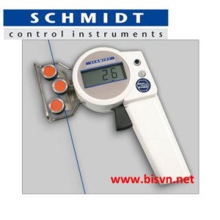
I keep thinking of measuring the pulling force directly using something akin to a tension meter.

see:
tension-meter-zed-hans-schmidt-may-do-luc-cang.jpg
Upstream of the actual pulling wheel, the filament rolls between three extra pulleys in a triangle arrangement, two pulleys on one side and the middle pulley opposing, and which moves up and down with respect to the line tension.

See:
https://www.google.com/search?q=ten...ved=0ahUKEwiFu865n-_RAhUor1QKHTSQCvkQ_AUIBygC

With a photodiode arrangement or a load cell of some sort, it would be easy to DIY something like this, using a weight or spring as the test force.

To grasp the feel of this arrangement, the counterbalance spring or weight is set so it is in correct proportion to be sensitive and sit in the middle of travel of the moving pulley, and then changes in tension would result in significant movement of the sensing pulley/shadow casting artifact like a little slot, etc.

Perhaps a wheel at the end of a lever pushing on the line under spring force or a weight, like a chain tensioner, would be enough to have a counterbalance situation.
The 3 pulley model would probably be more accurate and less prone to the line coming off the sensor pulley, etc.

But I bet something like this could achieve the delicate measurement precisely, and then it's a matter of the subpixel shadow sensor, PID and the motor torque control.
For torque control, you can vary the motor current via PWM motor controller.

Of course, we are comparing this method to that of measuring the filament thickness directly. I am thinking the thickness is important if one needs a mm diameter, but when
thickness is used as the metric for controlling the pulling force, it's like one step behind; the tension will change before the thickness, so measuring tension directly would result in
a faster and more precise control loop I think.

After reviewing this, perhaps do both, where mm diameter controls the setpoint for the tension by PID loop 1, and then this target tension is maintained via the tension meter PID loop 2.
It's more complicated, but probably more robust. The mm diameter is like the intergal, a slower accumulation of error, and the tension is more akin to the Proportional.

I saw this arrangement in servo driven cnc machine PID loops, that had both motor encoders and a linear glass encoder. The linear encoder was used for the Intergal, or accumulated reality, and the motor encoders used for the
faster parts of the feedback.

It would be a challenge to tweak two loops working in tandem, but once parameterized, it would be nice, no?
 
Last edited:
Status
Not open for further replies.
Back
Top