Teensy 3.6 with RA8875 TFT

Status
Not open for further replies.
OK - thanks again Kurt.

I've ordered a 2nd T3.6 (i needed a spare anyway) and I'llmuse that on my Protosetup - to see I I can get this working.

In the meantime do you know of a good source or reference point that clearly explains the differnt functions of the Layer Effect
ie layerEffect(enum RA8875boolean efx);//LAYER1, LAYER2, TRANSPARENT, LIGHTEN, OR, AND, FLOATING.

I'm struggling to fully understand teh behaviour of layers based on pure expirmentation.

Layer1 / 2 i've confirmed as show layer 1 only & show layer 2 only. But how do I get to show both layers again?
But as for teh rest - I just cant seem to work it out.
Its almost like is does different things each time it runs.
 
Last edited:
Hi - do you think the RESET pin wouldmake a difference?

Although I define it (as I'd copied code from somewhere at one point) - becasue I saw somewhere that it wasnt required, I'm not physically connecting a teh RESET on teh RA8875 board to my Teensy.

I think you should try connecting it. It seemed to be required in practice on my hardware.

Also, a note for later on - I had to lower the SPI_MAX_SPEED (can't check the actual define name right now but that should be enough to find it) in order to work on my 3.6. 22MHz that was defined for the 3.2 had very slow operation. This could be hardware specific so don't take it as gospel. I lowered mine to 18MHz max speed for Teensy 3.6 and it operates normally again.
 
BossRedMan: sorry as for how the things in library work, hopefully someone like Sandalhat who use them can answer.

As for where to change SPI_MAX_SPEED:
My guess is:
<where your library is>\_settings\RA8875UserSettings.h at about line 189
 
OK - so recieved my 2nd T3.6 today.
Hooked it up to the RA8875 (5") display using the SPI2 pins. (in my proto setup).
NOTE: Also connected the RESET pin on RA8875 to a T3.6 I/O pin (ie 33).
Also left the 'RA8875UserSettings.h' as defaults.

Loaded my test sketch - and bingo - it appeared to work first time.

One strange anomoly however, was I was getting random lines (of various lengths, thicknesses, colours & orientation).

So I changed the SPI_MAX_SPEED as advised by sandalhat

Code:
#if defined(__MK20DX128__) || defined(__MK20DX256__)  || defined(__MK64FX512__) || defined(__MK66FX1M0__)
        const static uint32_t MAXSPISPEED    = [B][U][COLOR=#FF0000]22000000UL;[/COLOR][/U][/B]  //don't go higher than 22000000!;

to 18000000UL;

.. & I think this has appeared to do the trick.

Also tried without the RESET connected & this works too.
So not sure what the actual issue was,?
Maybe a bad wiring or a bad Teensy3.6.

I'll try and get the new T3.6 plugged into my actual project in teh next few days to see if there is something in my project casuing teh original issue.

So a couple of things.

1] Thanks to you all for your help in getting me up & running (atleast I'm now getting graphics with the T3.6 & the display).

2] What will be the impact of changing this performance wise?
I'm not looking to do too much with this display.
A little 'psuedo' animation at start up & then simple graphics display plus a moving progression bar type display for a Tuner.


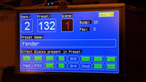
20161130_174243.jpg
 
Glad it is working. Maybe in my branch I will change the 22 to 18 as that is what appears to work for you.

I am not sure how much of an impact you will notice performance wise between SPI and SPI2. Yes SPI has a queue of 4 vs the SPI1 and SPI2 have a queue of 1. But as this code is not really geared to doing all of the Teensy tricks for knowing the Queues instructions and the like, my guess is probably not much.

As for 22 vs 18. obviously a little, but if you look under a scope you will see more of the time issues with are there any delays between commands versus how fast each output is. So I would stick with the one that works reliably.
 
I really wouldn't expect to notice a difference between 22Mhz and 18Mhz with this display. From poking through the library and documentation, it seems some (many?) of the calls are limited to 10Mhz, which is taken care of by the library automatically. Anything that isn't limited is allowed to go up to the user defined max speed. I tried a lot of different speeds when I was tinkering with my project and I honestly had to lower it well below 10 to notice a difference.

As for handling the pseudo animations and the animation required for the tuner you mention, I think it'll perform really well. I built a MIDI controller as well. Mine has a little progress bar on boot, as it's actually doing enough that the startup takes a second or so. I also have a slider for brightness. I was worried about the slider not performing well but it actually is really nice. I think the biggest thing to making the animations smooth is to avoid "blanking" and redrawing the same thing, which will cause flicker. This would be like if you draw a black (or whatever background color) rectangle over the whole slider and redraw it at the new position. Instead of doing that, remember the last position, draw over that, then draw the new position. In other words, try to be as smart about redrawing areas as you can and there will be minimal flicker on fast animations.

Here's an example of my function to draw a slider. It basically uses the fact that I update the screen before updating the actual brightness level. That way it can just draw over the position associated with the current brightness. I only change the brightness through the slider so it never gets out of sync. The "first time only" section basically draws something that isn't foreground or background color to avoid another issue I was seeing with my screen. I'm not sure if it's worth getting into here because I don't have any idea if it's just me or not. It seems like the RA8875 might attempt to not draw an area if it thinks you are drawing the same color, so I have do to that duct tape once like you see. If I understood it better maybe I could come up with a better way of handling that.
Code:
void drawBrightnessSlider(int x, int y, byte sliderPosition, int foregroundColor, int backgroundColor) {
  byte w = 255;
  byte h = 14;
  byte w2 = 50;
  byte r = 7;
  byte o = 2;
  if (firstTimeOnly == true){
    bigTFT.fillRoundRect((x - h/2),(y-255-w2),h,w2,r,0x1234);
    firstTimeOnly = false;
  }
  int oldValue = (y - lcdBrightnessRaw - w2);
  bigTFT.fillRoundRect((x - h/2),oldValue,h,w2,r,backgroundColor);
  int sliderValue = (y - sliderPosition - w2);
  bigTFT.drawFastVLine(x,y,w,foregroundColor);
  bigTFT.drawFastVLine(x,(y-w-w2-1),w2,foregroundColor);
  x = x - h/2;
  bigTFT.fillRoundRect(x,sliderValue,h,w2,r,foregroundColor);
  bigTFT.fillRoundRect((x+o),(sliderValue+o),(h-(2*o)),(w2-(2*o)),r,backgroundColor);
}

Another thing to play around with is the ability of the library to use custom fonts. If you don't like the basic font, or just want to be sure and get the best resolution for the size you need, you can easily create new files using the guide on sumotoy's wiki. I think you need to get his later version of the library though rather than the one included with Teensy (although I'm not current on my Teensy install so that information might not be right anymore). Speaking of which, I don't know which one Kurt has been modifying so maybe that would be extra trouble. Either way, for me it was worth the trouble to get the right version off github and figure out how to convert and use fonts.
 
Last edited:
Sorry for slow response been busy.

Thanks for the advice - will keep it at 18Mhz for now & see how it performs.

I've now integrated the new T3.6 into my main project (FYI - it's a midi foot controller for a Guitar processor - AxeFX2) and am now working to convert my old 'LCD' code to 'TFT' code.

Most things are transitioning OK with the exception of where I'm trying to use layers in the new 'TFT' code.

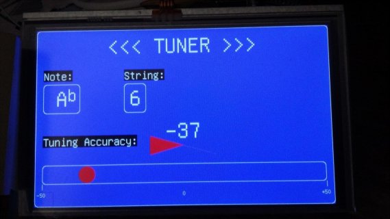
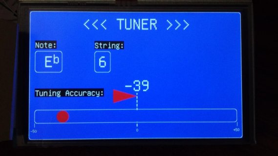
Eg - I have a tuner function, that if I recieve a tuner position msg from teh AxeFx it displays it on the screen as a horizontally moving ball.
Center position is 'Tuned'.
I'm trying to mark the center position with a dashed vertical line.
To prevent the line being over-written by the ball as it moves, I draw the dashed line on Layer 2.
But I just can't get it to show.

Here's how my code is laid out:
If the Tuner Button is pressed & the tuner WAS off - then I turn the Tuner on & call 3 x TFT related functions (to draw the Text & Boxes on Layer 1 & the dashed line on Layer 2):

Code:
if ( bouncer17.fallingEdge())                                                       
       {
          Tuner_Status =! Tuner_Status; 
          delay(50); 

          if (Tuner_Status==true)
          {
              tft.writeTo(L1);
                tft.clearScreen(RA8875_BLUE);
                tft.setRotation(2);
                tft.brightness(226);
                draw_TUNER_boxes();
                TUNER_Box_Headers();
                draw_TUNER_Dashed();

                MIDI.sendControlChange( 15, 127, 1 );  //If Tuner OFF - turn Tuner ON
          }

Code:
void draw_TUNER_Dashed()
{
    //Tuner Accuracy Center/Dotted Line - NOTE: USES LAYERS TO PREVENT DOTTED LINE BEING OVER_WRITTEN.
      tft.writeTo(L2);
          for (int j = -1; j < 2; j++)
          {
            for (int i = 0; i < 10; i++)
            {
              int new_y = Tuner_Box_4_V_Pos - 80 + (i * 10) + (i * 5);
              tft.drawFastVLine(Tuner_Box_4_H_Pos + j + (Tuner_Box_4_Width / 2), new_y, 10, RA8875_WHITE);
              tft.drawFastVLine(Tuner_Box_4_H_Pos + j + (Tuner_Box_4_Width / 2), new_y + 10 , 5, RA8875_BLUE);
            }
          }
      tft.writeTo(L1); 
}

When a Tuner msg is recieved it calls the main TFT Tuner function -
Code:
TFT_Tuner();
..which draws the ball at what ever position.

I've put delays in various places to see if the dashed line is displayed but quickly gets over-written.
It's not - it just does NOT display.

20161206_114140.jpg

If I remove the 'tft.writeTo(L2);' line then it displays the dashed line but a section gets overwritten by the ball.
Any ideas pls?
20161206_110652.jpg

One thing to note - is I have these different sections of code on different tabs with the sketch.
could that be influencing things in any way?
 
hello can I ask if you are using and touch screen
I have teensy 3.6 with Ra8875 7 inch display and I am using also this modified Sumotoy library with SPIN and works great but I cannot make it compile if I use the Capacitive touch and include library i2c_t3.h instead of Wire library
I need to use the i2c_t3 library because my i2c pins are 37 & 38
 
Using i2c_t3 is usually an all or nothing type of arrangement. That is if you use it, then all of the libraries that use/include wire.h need to be updated...

As for having to use i2c_t3 because you are using pins 37 and 38...
You can use those pins with Wire as well.
These are valid pins for the Wire1 object. And actually the default pins for this Wire1... So you simply need to change your touch code to use Wire1 instead of Wire.

Not sure which library you are using with Touch... Would be great if we could over time update some of these libraries to allow us to pass in either which pins or which Wire buss to use.

In my case if I use i2c_t3 master scanner I see that the touch screen connected to pins 37 and 38 is Wire2 , Would Wire2 also work with Wire library ? as I cannot make it work


---------------------------------------------------
Bus Status Summary
==================
Bus Mode SCL SDA Pullup Clock
Wire MASTER 19 18 External 416666 Hz
Wire2 MASTER 37 38 External 416666 Hz
Wire3 MASTER 3 4 External 416666 Hz
Wire4 MASTER 57 56 External 416666 Hz
---------------------------------------------------
Starting scan: Wire
No devices found.
---------------------------------------------------
Starting scan: Wire2
Addr: 0x38 ACK
---------------------------------------------------
Starting scan: Wire3
No devices found.
---------------------------------------------------
Starting scan: Wire4
No devices found.
---------------------------------------------------
 
Not sure which version of library you are using or which test program you are using...

As the Wire objects are Wire, Wire1, Wire2 and Wire3... Actually I think it is a bug in his test program... That is the code is doing:
Code:
Serial.printf("Wire%d  ",Wire.bus+1);
And I am guessing for Wire1, the bus is set to 1 and as such prints out 2...

Again from I2C header file:
Code:
// ------------------------------------------------------------------------------------------------------
// Initialize I2C - initializes I2C as Master or address range Slave
// return: none
// parameters:
//      mode = I2C_MASTER, I2C_SLAVE
//      address1 = 1st 7bit address for specifying Slave address range (ignored for Master mode)
//      address2 = 2nd 7bit address for specifying Slave address range (ignored for Master mode)
//      pins = pins to use, options are:
//          Interface  Devices     Pin Name      SCL    SDA
//          ---------  -------  --------------  -----  -----    (note: in almost all cases SCL is the
//             Wire      All    I2C_PINS_16_17    16     17      lower pin #, except cases marked *)
//             Wire      All    I2C_PINS_18_19    19     18  *
//             Wire    3.5/3.6  I2C_PINS_7_8       7      8
//             Wire    3.5/3.6  I2C_PINS_33_34    33     34
//             Wire    3.5/3.6  I2C_PINS_47_48    47     48
//            Wire1       LC    I2C_PINS_22_23    22     23
//            Wire1    3.1/3.2  I2C_PINS_26_31    26     31
//            Wire1    3.1/3.2  I2C_PINS_29_30    29     30
//            Wire1    3.5/3.6  I2C_PINS_37_38    37     38
//            Wire2    3.5/3.6  I2C_PINS_3_4       3      4
//            Wire3      3.6    I2C_PINS_56_57    57     56  *
//
 
Status
Not open for further replies.
Back
Top