Teensy LC - DAC faulty voltage

Status
Not open for further replies.
I did a specific project with a Teensy 3.2 where I needed also a DAC output, which worked very well and correctly.
For this specific application, the 3.2 looked overschooted, so I bought some LC's to do the same job, but the 1st one that I tested, could not go higher dan 1.58V on the DAC pin/A12
So I test it again with a very small program just to test the DAC and I got the same results.
////////////////////////////////////////////////////////////
int DACpin = A12;
int bitnumber = 4096; // maximum 12 bit

void setup() {
pinMode(DACpin, OUTPUT);
analogWriteResolution(12); // 12 bit resolution
}

void loop() {
analogWrite(DACpin, number);
}
////////////////////////////////////////////////////////////////////
RESULTS (Measurements)

with bitnumber = 512 -> 0.410V seems +/- 1/8 of 3.3V so OK :)
with bitnumber =1024 -> 0.81751 V seems +/-1/4 of 3.3V so OK:)
with bitnumber = 2048 -> 1.56995 V not excactly the 1/2 of 3.3V
with bitnumber = 4096 -> 1.58V instead +/- 3.3V -> NOT OK

So everything above +/ - 2000 -> 4096 gives 1.58V.

I did the test with 10 bit resolution and it also stocks at the 1/2 of 3.3V from +/- 512bit -> 1024 bit

What can be the problem? A bad LC or something else?
 
I haven't played with the DAC yet but should you have tried 4095 (binary 12 1's in a row) instead of 4096 (binary 1 1 followed by 12 0s in a row).
 
Last edited:
I haven't played with the DAC yet but should you have tried 4095 (binary 12 1's in a row) instead of 4096 (binary 1 1 followed by 12 0s in a row).

Yes of course 4095, but the fact is that the DAC voltage didn't change anymore above the value 2000 and limits at +/ half the maximum voltage of 3.3V.
Thanks for the reply.
 
Well that was FUN .... don't do :: pinMode(DACpin, OUTPUT);

Try this::
Code:
int DACpin = A12;
int [COLOR="#FF0000"]bitnumber[/COLOR] = 4096; // maximum 12 bit

void setup() {
[COLOR="#FF0000"]// pinMode(DACpin, OUTPUT);[/COLOR] // This pinMode sets the pin to a bad state
analogWriteResolution(12); // 12 bit resolution
}

void loop() {
analogWrite(DACpin, [COLOR="#FF0000"]bitnumber[/COLOR]); // Sample as provided had the wrong variable name here
}

Test code- open Serial Monitor - every time you hit 'Enter' the ( LED Toggles), value output changes higher until it is wrapped:
Code:
// https://forum.pjrc.com/threads/40259-Teensy-LC-DAC-faulty-voltage?p=125002&viewfull=1#post125002
#define qBlink() (digitalWriteFast(LED_BUILTIN, !digitalReadFast(LED_BUILTIN) ))

const int DACpin = A12;
int aValNumber = 0; // maximum 12 bit
bool delta = 1;

void setup() {
  pinMode(LED_BUILTIN, OUTPUT);
  qBlink();
  Serial.begin(57600);
  while ( !Serial && millis() < 2000) ;
  analogWriteResolution(12); // 12 bit resolution
}

void loop() {
  if ( delta ) {
    analogWrite(DACpin, (int)aValNumber);
    delta = 0;
  }
}

void serialEvent() {
  if ( 10 == Serial.read() ) { // update out value on each 'Enter'
    qBlink();
    aValNumber += 256;
    delta = 1;
    if ( aValNumber > 4096 ) {
      aValNumber = 0;
    }
    Serial.println( aValNumber );
  }
}
 
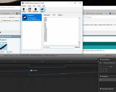
For what it is worth, I ran defragster's program (although i got rid of serialevent ;)

I hooked it up to my Saleae logic analyzer with both digital and analog output for the DAC pin.
tlc-AnalogWrite.jpg
And it looks like I am hitting 3.3v as you can see where I had the mouse pointer when I hit print screen.

I also wondered about the 4096, but the code in analogwriteDAC0 checks if > 4095 and sets it to 4095
 
I considered doing a timed jump instead of serialEvent() - but controlling the change and limited spew fit my purposes until I saw the problem. I'm using a dumb DVM so fast/uncontrolled changes weren't welcome :)

Before I got there I found this sin wave example that failed using setup() above until I saw the problem was the carried over pinMode:

Paul has noted before (IIRC the right context?) that the ASSERTING of 4095 is by design on 4096 - my code hit that and I saw 3.2V so I left it that way
 
The problem is this line:

Code:
  pinMode(DACpin, OUTPUT);

Do NOT put the pin into GPIO mode if you're going to use it as analog.

By turning on the digital output driver, you're causing the digital GPIO to drive the pin low at the same time as telling the DAC analog circuitry to drive it to 3.3V. The result is some random voltage somewhere in the middle.

Just delete that pinMode line, and fix the other minor errors in your code, and the DAC will work properly.
 
Dear Paul,

I am out of the office until the weekend. I will try it as soon as possible and I will let you know the result.
I understand the problem of the GPIO mode. Thank you very much.
 
Dear Paul,

I have just tested it and the DAC on the LC is working perfectly. Thank you for the tip. The DAC is working fine over the whole range, so everything is OK and solved.
 
Status
Not open for further replies.
Back
Top