Power restart on Teensy 3.6

Status
Not open for further replies.
Paul, I think the isolation converter is fine and will check that some time down the road with one I can connect directly, it provides a 5 V output. That was not possible this time, I had to use one with a 12 VDC output for other components. BTW the rise time for the isolation converter is a maximum of 3.5 msec. The one I am currently using is available at Digikey and likely other places. The part number is JCA1012S12, the data sheet is attached.
View attachment XP-Power_SF_JCA10.pdf

The buck converter is an el cheapo from China via Ebay. I have one more available and more to come. I can put one in an envelope for you. The specs are:
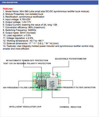
Screenshot 2016-12-01 08.48.41.png

I think what is happening at the 1 to 2 V level is that the two converters are fighting each other during start-up control. This can possibly be overcome with an extra capacitor, which I used before but then the rise time will be even slower and the system does not start up. Without that 1000 uF capacitor now, it does start up every time (only tried 5 to 10 times or so) with a short delay. If I get time later today, I will solder that capacitor or a 330 uF one back in and see what happens.
 
OMG! it has a "adjustable potentiometer".. !!!11!
thats better than a non-adjustable potentiometer, for sure.
SCNR :rolleyes:

Kurt:
If it's reproducable, the BEC is reproducable not good enough.
easy enough... ;-)

Did you try the capacitor on reset ?
 
Hi guys:

May want to play some more, but: I know from previous setup, it worked fine with T3.2, as it came off of my PhantomX, and the power fed both the ODroid XU4 as well as my Teensy board.
It also worked on T3.5 with my castellated board soldered on it. It also worked on the V1 Beta T3.6 board, but has reproduced so far on two of my different T3.6 boards (The one Paul fixed and the one that is sort-of like Frank's flexi board).

Actually this one does not have a flexible Pot ;), there is a larger CAP sticking out the top. You can however change the BEC to output different voltage, by using their "Castle Link", which I think is: https://www.amazon.com/Castle-Creations-Link-Programming-Adapter/dp/B000BOG8V0

I don't have any of their link's, but may have a 2nd one of the BEC floating around here.

I have not tried adding CAP on reset yet. Also maybe should try on straight T3.6 without other stuff on it.

Again wondering if there is any other data that would Help? Likewise I may have a few other brand ones floating around as well.
 
What does powering a simple blink on a T_3.2/3.5/V1b3.6 in Parallel with T_3.6 not currently running alone?
 
I have not tried adding CAP on reset yet. Also maybe should try on straight T3.6 without other stuff on it.
I tried with the first Cap I found that I could plug into breadboard, which was a 10uf ALUM 16v... And it did not boot... May look around but I think I tossed most of my older through hole parts awhile ago.

Anyway to verify it was not my board design that was doing the issue, I just soldered on headers on new T3.6 (in preparation for usage in the next board I solder up. I programmed Blink onto it, worked fine.
Tried connecting up again with output of BEC to VCC and GND and again no blink. If I again disconnect the plug from the output side of BEC and plug back in, then blink runs...

What does powering a simple blink on a T_3.2/3.5/V1b3.6 in Parallel with T_3.6 not currently running alone?
? Are you asking if I hook up the output from the BEC to multiple boards?

Connected power from Breadboard to T3.5 and T3.6 and then plugged in power. T3.5 blinks and T3.6 does not...
 
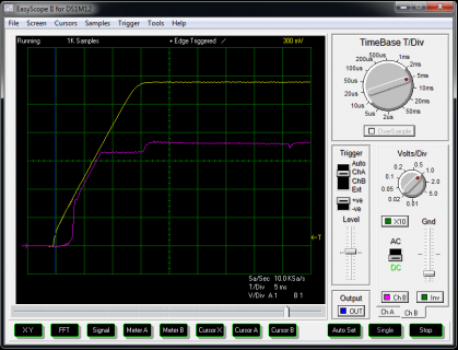
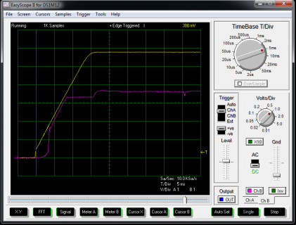
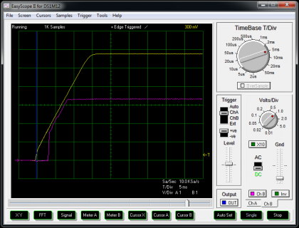
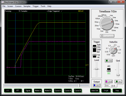
Here are some more screenshots for both the 3.5 and the 3.6 with two different capacitors - 330 and 1,000 uF - added to the 5 V supply.There is virtually no difference in rise time between the 330 and the 1,000 uF capacities being connected, however the curves do have a slight difference. Interesting too is also the 3.3 V trace difference between the 3.5 and the 3.6 Teensy. The 3.5 starts up without a problem, the 3.6 does not with either the 330 or 1,000 uF capacitor in the supply. The 3.6 does start up without any of the capacitors.

Screenshot 2016-12-02 09.13.50.png
This is the 3.6 with a 1,000 uF capacitor on the 5 V supply. The yellow trace is 5 V supply siting at 5.7 V and the magenta trace is the 3.3 V on the 3.6.

Screenshot 2016-12-02 09.18.02.png
This is the 3.6 with a 330 uF capacitor on the 5 V supply. The yellow trace is 5 V supply siting at 5.7 V and the magenta trace is the 3.3 V on the 3.6.

Screenshot 2016-12-02 09.19.37.png
This is the 3.5 with a 1,000 uF capacitor on the 5 V supply. The yellow trace is 5 V supply siting at 5.7 V and the magenta trace is the 3.3 V on the 3.5.

Screenshot 2016-12-02 09.18.23.png
This is the 3.5 with a 330 uF capacitor on the 5 V supply. The yellow trace is 5 V supply siting at 5.7 V and the magenta trace is the 3.3 V on the 3.5.
 
? Are you asking if I hook up the output from the BEC to multiple boards?

Connected power from Breadboard to T3.5 and T3.6 and then plugged in power. T3.5 blinks and T3.6 does not...

Yes, as you did "Parallel" - I wondered if two would run at the same time ( BEC has the current ) and if the T_3.6 would still fail while the other ( T_3.5 ) worked seeing the same power on supply.

I figured it would be an easy test - doesn't give a reason for the behavior - but suggests there is some net difference in how the T_3.6 starts up given the same supply startup. The Skiddy scope shows the 3.3V take 15ms to peak? And then surges. I wonder where in there the MCU starts ticking and Teensy setup starts - maybe that surge at ~20ms?

I wonder if it is the jump to hsrun or something else unique to T_3.6? What happens if compile for T_3.6 at 120 MHz or lower? Perhaps throw in a delayMicroseconds(15000) at the top of init_pins() and maybe in main.cpp before _init_Teensyduino_internal_();

Though the V1bT_3.6 running gets by - that may be from the different MCU package - or alternate net capacitance or change due to the unique PCB.
 
Skiddy
Your scope shows maybe 3.65V on the 3.3V supply. Thats to high, the 3.6 is spec'e 3.6 V max, the 3.5 is 3.8V max. Somethings pulling it up. The LP38691 regulator on the Teensy 3.5 & 3.6 has max worst case 3.43V but more likely 3.36 max.
 
Thanks for pointing that out bicycleguy. It was 3.3 at first and then had that strange increase, I will have to have a look what is happening at that time. Interesting too that it is perfectly normal with the 3.5.
 
Yeah - I noted that surge in my post 34 - wondering if that is where it goes bye-bye - Kurt - does your 3.3V line do that? Any change with 120 MHz or delays at 180+ in startup?
 
Here is not much of an update.

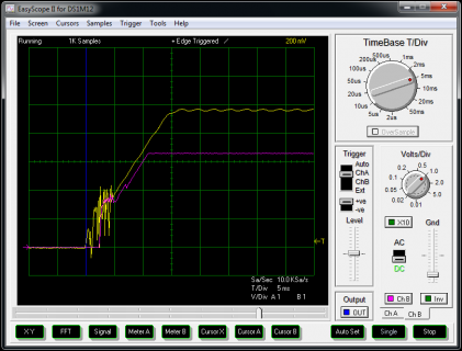
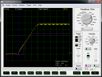
Still am using the 3.6 in this case but it may be a different one of the few I have in the box, I did not keep track of it. On my board hardware has not been changed, however the firmware has been expanded. Only a few visible changes have taken place on the response. The yellow trace is the feed to the Teensy 3.6 and the magenta one is the 3.3 V on the Teensy board.

Screenshot 2016-12-07 14.19.28.png
Above is the response without any external capacitor to the buck converter. The Teensy does start up within a time frame that seems normal to me.

Screenshot 2016-12-07 14.18.55.png
Above is the response with a 1,000 uF external capacitor to the buck converter. The Teensy does not start up.

Apart from the squiggles without using the extra capacitor the only visible change on the 3.3 V is the delayed startup, which is about 1 msec, when the capacitor is used.

Edit: In a few days I will update this again using a different power supply and thus eliminating the buck converter.
 
@skiddy - was that sketch for pic 2 [Teensy does not start up] compiled over 120 MHz? Does it act the same at or under 120 MHz?
 
@defragster - the sketch from post 13 was definitely run with the 3.6 at 180 MHz without success. However keep in mind, that the 1,000 uF capacitor was in parallel to the buck converter at that time. It is unlikely that I tried the 3.5 then, I was definitely switching back and forth between the 3.2 and the 3.6 though. Of course the 3.2 worked.

There has never been a problem starting up the 3.5 with or without the extra capacitor with the complete sketch. The sketch from post 13 was only for demonstration, the entire sketch compiled is now 280 Kbytes plus.
 
Defragster: Tried 120mhz and did not do much if any change with that BEC.

screenshot.jpg
The Three channels being shown are: VIN, +3.3v and Reset
 
Defragster: Tried 120mhz and did not do much if any change with that BEC.
The Three channels being shown are: VIN, +3.3v and Reset

Good to know Kurt - that should rule out the jump to HSRUN power levels as the reason for the spaz. Other than an being entirely different MCU - that's the only part you have any control over.

That and in post #34 I wondered the effect of:
Perhaps throw in a delayMicroseconds(15000) at the top of init_pins() and maybe in main.cpp before _init_Teensyduino_internal_();
 
Hi Defragster,

Note: with current sources, I don't believe theire is init_pins. It is defined in one header file and commented out in two source files.
I believe the current function is _init_Teensyduino_internal_(void) and is called from ResetHandler which also calls main.

I was thinking of trying to debug some of this, Not sure how. That is it would be great to see where it gets in ResetHandler, but a lot of this is done before IO pins are init, so I can not toggle pins and the like.
Thought about enable Serial1 writes, like there is some commented out code to init the Serial1, but the init is for TLC I believe. Can probably hack up a version for T3.6, but as this is done before the CPU speed is set, not sure what values to use...

Might be nice to be able to hook up hardware debugger, but not sure what steps that take or what hardware/software combos it would take. I do have AVR stuff and I do have one that I could program the Trossen Arbotix Pro earlier which has an M0 in it. ...
 
Note: with current sources, I don't believe theire is init_pins. It is defined in one header file and commented out in two source files.
I believe the current function is _init_Teensyduino_internal_(void) and is called from ResetHandler which also calls main.

opps - Red Herring with init_pins - the idea - as noted with main.cpp - before anything gets going to give it a wait before any MCU specific setup or clock adjustment gets running - make sure the voltage is where it should be. If that doesn't do it then I wouldn't see it being a software controllable race condition but rather electron based one.

I was going to mention from my vast knowledge - i.e. reading an email from my EE buddy that I can't locate now - that a bit too much capacitance in the wrong place can spoil a power supply (not sure if it was LDO or switching). He noted in email back a couple months one of his creations was suffering an anomaly (internal to his PCB supply) that turned out to be from that. Not sure if that applies to your BEC or the BUCK supply from Skiddy.

You said your hand 'Erin' built KS Beta 2 T_3.6 runs fine where the KS doesn't do this - or was that only the Beta 1 mega board that is wholly different?
 
Yep - The hand built Beta 1 did not show this issue, but the ones from Kickstarter and/or purchased appear to.

It is a switching regulator, which I have used with other Teensy as well as Linux boards.

Will experiment later
 
Today I was finally able to test the 3.6 without the extra a buck converter. Now I am getting 5 VDC directly from an isolation DC/DC power supply, which goes directly to the 3.6. The quick answer is that it did not work with my sketch. However it worked fine with the extracted sketch shown in post 13. After editing out everything else using the SPI connection besides the TFT, it still did not work correctly with the complete sketch on the Teensy 3.6 but it continues to work fine on Teensy 3.5. Even turning the power off and on quickly, I was unable to get the TFT started properly using the Teensy 3.6. The Teensy 3.6 itself though does seem to work, because the small LED blinks in a similar rhythm as it does on the 3.5 with the TFT screen working.

So it seems previously there were problems with the power supply as well as the firmware showing up with the Teensy 3.6 but not on the 3.5.

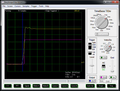
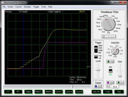
The power rise looks much better now and is less than 1 msec.

Screenshot 2016-12-10 14.09.16.png
Here a screenshot with the same settings as before

Screenshot 2016-12-10 14.14.34.png
The same but with a different time base
 
Last edited:
Hey Guys,
Just discovered this conversation when I was having a similar problem with a Teensy3.6. Works fine on USB delivered power, didn't seem to boot on Vin (+5v) power when that +5v was delivered from my Rigol DP832 PSU.
BUT, if I just pulled the +v jumper out of my breadboard and put it back in, the Teensy then booted every time. Didn't matter how long I pulled it out for.
I messed around with even powering the Teensy from 3.3v directly, bypassing the onboard reg, but still got same behaviour.
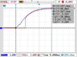
After reading this thread I had a look at my PSU on my scope and yes I was running into same problem as you guys. My PSU has quite a slow ramp up time and RESET was going from LOW to HIGH on the Teensy before the PSU had reached 3.3v.
NewFile1.png
Blue is "3.3v" from my PSU to 3.3v pin on Teensy. Red is the RESET pin.
So RESET was coming up after maybe 8mS and the power rail was not reaching 3.3v til about 30mS!
As I'm only using this PSU for some bench testing, I will check what my real project mini PSU does next, hopefully its way faster than the DP832.
 
Is it the MKL02Z32VFG4 processor that holds RESET for the main MCU LOW and then takes it HIGH? Is so, perhaps extending the time it waits before releasing RESET to HIGH would make the Teensy more PSU tolerant?
 
Status
Not open for further replies.
Back
Top