Hi, I am trying to plan the driver that I should build for the teensy audio board before feeding it with Piezo electric - high impedance sensor,
my source is a guitar piezo pickup, the impedance is high and not static (because I am gonna move it to a different guitars, which affects the impedance of the piezo sensor...)anyway I am trying to plan an active bandpass filter, cutting all the frequencies bellow 60Hz and higher than 20Khz (for noise cancelling and anti-aliasing)
I was searching for an OP-AMP that is available in a DIP version so I found this :
MICROCHIP MCP6024
and a Digital potentiometer, because I am gonna place the piezo sensors on a different instrument and it will recieve different signal, so I should amplify each of them differently. AD5204_5206.pdf
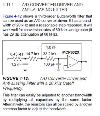
I can seen in the MICROCHIP MCP6024 typical applications (A/D CONVERTER DRIVER AND
ANTI-ALIASING FILTER)
Where should I add the low frequencies cutting? (cutoff in 60hz)
Where should I place the digital potentiometer to control the amp level?
and which will be the best kind of capacitors and resistors to use?
I tried to look at the store but there are too many kinds of caps and resistors...
Thanks in advance!
Alon
my source is a guitar piezo pickup, the impedance is high and not static (because I am gonna move it to a different guitars, which affects the impedance of the piezo sensor...)anyway I am trying to plan an active bandpass filter, cutting all the frequencies bellow 60Hz and higher than 20Khz (for noise cancelling and anti-aliasing)
I was searching for an OP-AMP that is available in a DIP version so I found this :
MICROCHIP MCP6024
and a Digital potentiometer, because I am gonna place the piezo sensors on a different instrument and it will recieve different signal, so I should amplify each of them differently. AD5204_5206.pdf
I can seen in the MICROCHIP MCP6024 typical applications (A/D CONVERTER DRIVER AND
ANTI-ALIASING FILTER)

Where should I add the low frequencies cutting? (cutoff in 60hz)
Where should I place the digital potentiometer to control the amp level?
and which will be the best kind of capacitors and resistors to use?
I tried to look at the store but there are too many kinds of caps and resistors...
Thanks in advance!
Alon

