Teensy Convolution SDR (Software Defined Radio)

DD4WH and Frank B,

thanks for your prompt reply and proactive comments. I had the correct Si5351 library loaded and xtal frequency selected. I worked a little longer on my setup, connected a proper antenna and got most AM broadband channels running, especially when using SAM demodulation. In fact, whatever AM or amateur band I select, I get some signals coming through which are clearly visible on the spectrum display. When I select WFM, however, I get nothing but loud white-noise and static. The spectrum display is blank. This is across the entire UKW band. Again, this is with the Elektor front-end. I've no idea. Maybe because I'm using a breadboard with jumper wires instead of properly soldering the components together ??
Thanks for any hints,
Les.

Yes,

have you enabled this:
//long calibration_constant = 108000; // this is for the Elektor PCB !
Set calibration_factor to 1.
For a first run, this should should work, but you have to calibrate it later.
(I think) this constant is needed, because the Elektor board has no caps on the crystal, and the 10pf from the Si5351 are not enough.
They really could have fixed that in later revisions - but they did not.


DD4WH can tell you how you to calibrate it better.
 
Thanks Frank B. Yes I did enable that constant. I've been using Si5351 in other projects and understand how to calibrate them (I think). I worked out the calibration constant for my Elektor board (using an arduino nano), which is linked to the onboard xtal so should be the same across platforms. So my calibration factor came to be 140000, which is what I'm using. Never the less, I go back and try your suggestion and will report back. I figured that if my calibration constant is out, the stations would not line up to the frequency shown on the display.
 
Unfortunately, no luck with varying the calibration constant. Still, I'd be interested to know what your process is to arrive at the correct number. I was looking at the I and Q signals on the output of the Elektor board with a scope, it's still seem something coming out....I need to drill into the workings of this, I feel my messy wiring is not helping...
 
Oh I have problems with WFM and the elektor-board, too.
It works.. but is noisy. You need a good antenna or even an amplifier.
 
I am new to the forum. Thank you DD4WH for the excellent work on the SDR. It is really interesting. So interesting that I bought all the parts and put one together.

I am using a Teensy 4 with the PCM1808 ADC and PCM5102A DAC and followed the pinout in the provided Excel file plus I added 100 Ohm resistors to the clock and MISO lines on my ILI9341 TFT display per Frank B's post. I have read all 14 pages of this thread. I am pretty sure I have built the DD4WH_T4 hardware correctly as far as I can tell. I have the HARDWARE_DD4WH_T4 define uncommented.

I am probably doing something dumb here, but my display shows nothing. If I load up the Adafruit graphicstest.ino (modified so the pins are correct per the convolutionSDR) the display works fine. When I load the latest (May 8 2020) Teensy_Convolution_SDR code, I get a white screen. The serial monitor shows "Found EEPROM version mr1... a bunch of filter coefficients... a couple of decimation stage number of taps, the FlexRAM-Banks and some info about the memory." The Teensy seems to be running okay.

If I enable the debug, I get the same info, then the twinpeaks counter counts up to 800 and then I get "microsec for 16 stereo blocks" and "n_clear 0" slowly repeats forever.
Am I getting stuck before the screen is written? I have been digging through the code and figuring it out bit by bit, but there is a lot of code!

I am an electronics engineer so the hardware doesn't scare me. My software skills are not so great, but I can follow most of the code. I don't have any trouble with the filters and FFT stuff.
Anyhow, if anyone has any ideas to share I appreciate it.
Thanks!
@WH7U: I guess you are nearly there :).
* it would be best, if you have the latest Teensyduino software 1.52 and use that for compiling
* the TFTs behave differently, even if they all say they are ILI9341 . . .
* try to substitute the lines

Code:
[TABLE]
[TR]
[TD]tft.begin(70000000,10000000);
[/TD]
[/TR]
[TR]
[TD][/TD]
[/TR]
[/TABLE]
[TABLE]
[TR]
[TD]int32_t iospeed_display = IOMUXC_PAD_DSE(3) | IOMUXC_PAD_SPEED(1);
[/TD]
[/TR]
[TR]
[/TR]
[/TABLE]
 
[TABLE]
[TR]
[TD]*(digital_pin_to_info_PGM + 13)->pad = iospeed_display; //clk[/TD]
[/TR]
[TR]
[TD][/TD]
[/TR]
[/TABLE]
 
[TABLE]
[TR]
[TD]*(digital_pin_to_info_PGM + 11)->pad = iospeed_display; //MOSI
[/TD]
[/TR]
[TR]
[TD][/TD]
[/TR]
[/TABLE]
*(digital_pin_to_info_PGM + TFT_CS)->pad = iospeed_display;

with
Code:
tft.begin();
Does that help?
 
Unfortunately, no luck with varying the calibration constant.

One recommendation:
* Do NOT mess with any of the calibration variables before you are perfectly sure, that everything is working correctly. Leave every calibration variable as it is !
* the frequency calibration is the most unimportant thing in this SDR, BUT: if you change the calibration variables like in your case, you will mess up the functioning, because it could mask other errors you made ;-)
* do not use manual IQ correction, leave the AUTO IQ correction enabled, that means you do not need to mess with IQ amplitude and phase calibration, it is automatically calibrated for every frequency that you tune --> much more accurate than you can calibrate manually
* My guess is that you do not have the right crystal frequency defined . . . for the Elektor board it must be 25MHz (and CLK1), is that your #define? [I conclude that from your calibration factor, which is absurdely off the track with 140000 . . .]
* PLEASE double-check again, that you have the right Si5351 lib by Etherkit, use the latest version of that lib and make sure you do not have another Si5351 library installed in Arduino. The SDR should not work at all with your absurdely low calibration factor with this correct lib . . .
 
It works!

Thanks for the help Frank and Les. I got it working!!!
When I was troubleshooting I hooked the TFT reset line to pin 6 of the Teensy. I forgot to put it back to 3.3V. Doh! A couple hours of my life I will never get back due to scatter brainedness. Not sure why it didn't work the first time - likely a wiring error on my part that got fixed when I rewired it.

Next step is to get an antenna hooked up and see if it is really working. But having the display going is a big help. I will keep you all posted on my progress.

This is a great project and lots of work by everyone. Building a top-end receiver is a challenge; and I just can't stand to have a second rate receiver - it bugs me when I keep thinking it could be better. This receiver has about the same specs as the really high end HF receivers on the market that cost more than my first car. I am excited to get it going and see what it can do. The only thing I think is needed is power supply isolation and shielding to make it into a full fledged communications receiver capable of operating in a transmit environment. But then I will need a transmitter!

How much horsepower does the Teensy have left over? I was thinking of taking a second Teensy with a separate TFT display to build the transmitter around just to keep from messing up the receiver project - it is really nice as is. We'd only need to add receive mute to the receiver which is really easy - just turn off the oscillator and maybe short the antenna input with a FET and add a TR relay to switch the antenna from transmitter to receiver.

Getting ahead of myself. I need to go hook up my antenna. ...after I run some errands.
Thanks guys. This is great.
 
Excellent to hear! Have fun with it, thats the goal ;-)

Does it work with the original tft.begin settings (70MHz) ?
 
Sounds exciting! I have to read more about that in order to understand what you did in the code!

Exactly that what is shown in the Blockschaltbild - but with the 19khz notch after the switches (was easier to use because that is what your version does - no rewrite needed)
The stereo separation is really good!
My code is a mess at the moment. I will update my github when I have the PLL for decoding the mpx signal working.
 
How much horsepower does the Teensy have left over? I was thinking of taking a second Teensy

Depending the mode and settings about 50%
But yes, I'd use a 2nd Teensy - this ensures you have enough power left for future extensions.
 
Excellent to hear! Have fun with it, thats the goal ;-)

Does it work with the original tft.begin settings (70MHz) ?

Yes it works with the original tft.begin settings.
I am using the TFT display from PJRC. Not sure if the resistors fixed it. I will mess with it and let you know. Thanks!
 
Depending the mode and settings about 50%
But yes, I'd use a 2nd Teensy - this ensures you have enough power left for future extensions.
I will do that. I think the transmitter will benefit from having its own TFT display as well. It will get too busy to add more to the receiver display.
 
The receiver is working great. The I2C resistors were not needed in the TFT lines (although a good idea). I must have had a wiring error.
I do get crashes in WFM mode in the US FM broadcast band but I need to clean up the wiring before I blame it on anything. The screen goes white and I need to reset the Teensy when this happens.
I am using a QRP Labs receiver. The I and Q level is very low so I plan to rework the gain on the op amps. But SSB and CW on 40m was fine. I just don’t see the weak signals on the spectrum display.
Anyhow, very happy to have a SDR up and running!
 
@WH7A: great to hear that!
Could be an option to lower the SPI speed for the TFT (70MHz), see one of my posts above.
The QRP labs receiver is great! But it uses an audio transformer after the OP amps which will probably not have a bandwidth wide enough to put through 240kHz needed for wideband FM . . . audio transformer typically have about 20kHz BW, but you can still give it a try, but do not expect superior sensitivity and audio quality in WFM. Also, the sampling caps and the lowpass filter caps in the OP amps of the quadrature sampling detector have to be substituted with smaller values in order to cope with the needed BW.
 
Good point. Those little laminated transformers are lucky to pass much above about 10 kHz as I recall. They are a good idea if running audio to a computer sound card but not for this application.
I can swap the caps easy enough.
I wonder if its worth spinning a pcb for a receiver? We could add a switch to enable/disable the f/4 on the oscillator. And optimize it for 240kHz BW audio. Maybe put some good power supply filtering on it for the analog parts to keep the digital noise out. Add an I2C demux for input filter switching, etc.
Except I keep forgetting that I have a job 😄
 
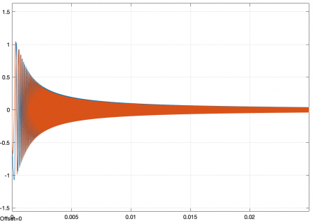
I was trying to figure out the values for the capacitors for the QRP Labs receiver to open up the high frequency response to make it work better on WFM. Figuring out mixers is a pain so I modeled it in Simulink. Attached is a plot of the modeled audio frequency response of the as-built receiver with the 100 nF capacitors on the output of the detector (I also removed the output capacitors and transformer). The amplitude drops to half at about 1600 Hz.
0-250kHz100nF.png
 
Changing the capacitors to 10 nF is getting closer. The amplitude is half at around 160 kHz.
0-250kHz10nF.png
 
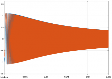
5 nF capacitors are just about right.
View attachment 20225
This was modeled with a 20 mV RF input signal at 1 MHz and the LO was swept from 4 X 1 MHz to 4 X (1 MHz + 250 kHz). The x axis is time in seconds and the y-axis is Volts. I set the time of the simulation to 25 ms so it is easy to see the sweep frequency (0 - 250 kHz).
I have not tried it in real-life yet but tomorrow I will see if I can find any 4.7 nF caps to test with.
 
WH7U, thanks for the update on the QRP Labs receiver. I just ordered one.

Coming back to my Elektor board struggle, I made some progress in figuring out why I don't get WFM reception on it.. First, let me state all other bands are working. I can receive short wave broadcast well, I can syncronize clock on 129.1K, all is fine. I used a calibrated signal generator and if I inject any frequency from 0-30Mhz into the Elektor board and I get the SDR's spectrum display correctly showing the signal and its strength. The default calibration values of the SDR are very close and certainly good enough to get the radio working. If, however, I inject signals approx 36Mhz and above, my Elektor board is falling apart. I looked at what the key difference if between the Elektor board and all others (QRP, Softrock, etc). Amongst many things, it is the main multiplexer chip, the Elektor board uses a HC4066 and the spec sheets state the max switching frequency of that chip is around 30 - 35Mhz. On the other hand, the other boards use the 3253 chip which can switch at approx 250Mhz (although the si5351 could not go that high). So, maybe the Elektor board is beyond it's capabilities to receive proper WFM. My question is: is there a success story here with the Elektor board and WFM reception ?
 
WH7U, thanks for the update on the QRP Labs receiver. I just ordered one.

Amongst many things, it is the main multiplexer chip, the Elektor board uses a HC4066 and the spec sheets state the max switching frequency of that chip is around 30 - 35Mhz. On the other hand, the other boards use the 3253 chip which can switch at approx 250Mhz (although the si5351 could not go that high). So, maybe the Elektor board is beyond it's capabilities to receive proper WFM. My question is: is there a success story here with the Elektor board and WFM reception ?

Hi Les,
I don't have an Elektor SDR so can't directly answer your question. But the 74HC4066 has a limited frequency response, plus the on-state resistance of the switches are about 10X that of the 3253. The Tayloe detector uses the switches to drive a capacitor so the on-state resistance is important.

Unfortunately, the 3253 has an internal multiplexer and the 4066 does not so you would need to add another logic chip to upgrade the Elektor to use a 3253 (I'm assuming - I don't have a schematic for the Elektor).
 
FM: The Elektor SDR works. With Stations > 100MHZ not good, stations around 87..95MHZ are better.
It does not work with weak stations .
I can't receive the local station, but a station100km away, 100kw works - noisy. The mono signal is ok.
 
Last edited:
Thank you for the responses. I'm not gonna modify / upgrade the Elektor board, will be using it for SW broadcast reception. I'm hunting for a better front-end, already ordered the QRP lab receiver.
 
Hello all together,

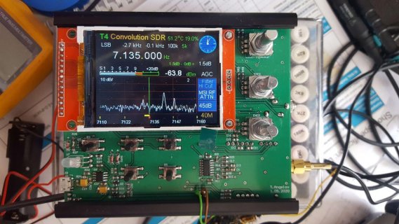
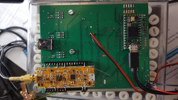
here is my short report about the MSI001 version of the Teensy-ConvolutionSDR.
20200525_125345.jpg 20200525_125458.jpg

Everything is designed to fit together with smal speaker and two Lion batteries in aluminium box from Hamond (1455N1202BK) (maybe a bit oversized - would fit as well in a smaler one :) ).
On the main board are placed the battery charger (TC4056), audio chip (SGTL5000), audio amplifier class D, diferential amplifier suming the diferential output of the MSI001 chip to single ended.
From the Panadapter (MSI001) board on the bottom the diferential I/Q signals are going out and the SPI interface is ging in.

For now with a wire approximately 2m hanging out of my window I was able to listen to HAM radio on 80m 40m and 20m and various broadcast stations as well as full FM range.
The MSI chip is opening totaly new frequenzy ranges, in the software added the 144MHz range, but there for now didn't spot anybodey (for now it is in experimental stage).

Here on the end comes one question from me about a implementation of an SNR indicator.
I folowed in the code that "NR_lambda[NR_FFT_L / 2];" used for the spectral noise reduction (line 2536) and further

Code:
// 5.  SNR CALCULATION: We calculate the signal-noise-ratio of the current frame T = X / M for every bin. If T > PSI {lambda = M} 
6301             //     else {lambda = E} (float32_t lambda [128]) 
6302 
 
6303             //            for (int bindx = 0; bindx < NR_FFT_L / 2; bindx++) // take first 128 bin values of the FFT result 
6304             for (int bindx = VAD_low; bindx < VAD_high; bindx++) // take first 128 bin values of the FFT result 
6305             { 
6306               NR_T = NR_X[bindx][NR_X_pointer] / NR_M[bindx]; // dies scheint mir besser zu funktionieren ! 
6307               if (NR_T > NR_PSI) 
6308               { 
6309                 NR_lambda[bindx] = NR_M[bindx]; 
6310               } 
6311               else 
6312               { 
6313                 NR_lambda[bindx] = NR_E[bindx][NR_E_pointer]; 
6314               } 
6315             }

But for me it is not really clear yet if this is the right way for the SNR indicator implementation.
I will be very grateful for some tips and hints :).
 
Back
Top