Scrambled PWM from Servo Function on Teensy 3.5

Status
Not open for further replies.

laptophead

Well-known member
I wrote this simple Servo algorithm based on a DC motor bringing a pot back to the central value.

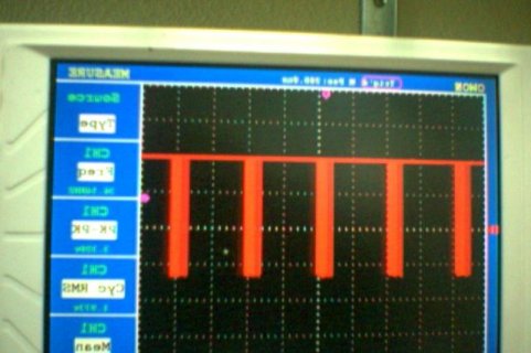
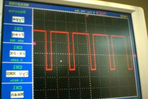
While the (GapFront >= 50) gives me a clean 200 PWM, the other condition (GapFront <= -50) gives me a scrambled signal.
I included the pics of the nice and bad PWM.
What I tried and did not work:
Moved pin 22 to pin 2.
Used a 100 digitalWrite val instead of 200;.

Please help.

Thanks a lot.
 

Attachments

  • Teensy_LegStudy.ino
    1.3 KB · Views: 72
  • Photo on 12-8-16 at 9.44 AM.jpg
    Photo on 12-8-16 at 9.44 AM.jpg
    46.3 KB · Views: 161
  • Photo on 12-8-16 at 9.45 AM.jpg
    Photo on 12-8-16 at 9.45 AM.jpg
    47.3 KB · Views: 101
The problem is with the if-else structure in your code.

Code:
  if (GapFront <= -50) { 
        analogWrite (FrontLegUpPin, 256);
        analogWrite (FrontLegDnPin, 100); // pin22 white wire
  }
  if (GapFront >= 50) { 
        analogWrite (FrontLegUpPin, 200);
        analogWrite (FrontLegDnPin, 256);
  } else {  // do nothing
        analogWrite (FrontLegUpPin, 256);
        analogWrite (FrontLegDnPin, 256);
  }

When GapFront is less than -50, you meant to execute only the first 2 analogWrite. But in fact, you're executing those first two, and then the last two, because the second "if" also gets checked, even when the first "if" is true. So you're rapidly setting the PWM to 100, and then 256, and repeating over and over as you read the analog signal, so you see that scrambled waveform.

You could fix the code several ways. For example, chaining if-else will cause only one of the 3 to run:

Code:
  if (GapFront <= -50) { 
        analogWrite (FrontLegUpPin, 256);
        analogWrite (FrontLegDnPin, 100); // pin22 white wire
  } else if (GapFront >= 50) { 
        analogWrite (FrontLegUpPin, 200);
        analogWrite (FrontLegDnPin, 256);
  } else {  // do nothing
        analogWrite (FrontLegUpPin, 256);
        analogWrite (FrontLegDnPin, 256);
  }
 
These sorts of problems are much easier to understand when your code has better formatting. Arduino's Tools > Auto Format can do most of the tedious work for you.

But you should also put a little work into positioning the curly braces well. Two styles are commonly used. In #2 you can see how I prefer to do it. The other common style looks like this:

Code:
    if (GapFront <= -50)
    {
        analogWrite (FrontLegUpPin, 256);
        analogWrite (FrontLegDnPin, 100); // pin22 white wire
    }
    else if (GapFront >= 50)
    {
        analogWrite (FrontLegUpPin, 200);
        analogWrite (FrontLegDnPin, 256);
    }
    else   // do nothing
    {
        analogWrite (FrontLegUpPin, 256);
        analogWrite (FrontLegDnPin, 256);
    }

Many people feel this style is easier to read, perhaps because the braces line up vertically, or maybe because of the extra white space. I prefer the more compact style (as do many people), mainly so I can see more code in the limited vertical space of my monitor. Almost all widely used code follows one of these two styles.

Both styles indent the conditionally executed lines, and both styles avoid mixing those lines with the braces.

These styles take extra time when writing your code, but that time is well spent. It takes a *lot* less time to format code clearly than is spent trying to understand why things don't work.
 
Last edited:
Talking about analogWrite for Teensy 3.5/6, is there any guidance regarding PWM resolution vs. frequency, like it appears for the classic Teensy? I could experiment - of course - but that would take some time.

Thanks!
 
The optimal (and quickest, if no pre-divider is involved) relationship can be calculated or found by the simple equation f_opt = F_BUS / (2^res_bits)
 
Thank you, Paul - you are super fast!

I am a bit disappointed; I was hoping for a performance increase proportional to the clock (2x-ish) but I guess I was looking at the wrong clock.
 
You might in fact increase the performance by overclocking the system bus. Freescale states a maximum of 60MHz and Paul's default implementation sets it in fact to the CPU clock, divided by an integer, to reach a speed close to the max spec:
When the CPU is clocked at 120MHz or 180MHz, the respective dividers are 2 and 3, which makes a F_BUS of 60MHz. With the CPU clocked at 96MHz, 144MHz, and 192MHz, the dividers are 2, 3, and 4, to obtain 48MHz. But forum member FrankB has made tests and discovered that the FTMs work still well at higher frequencies. That's why in boards.txt, there are hidden options to obtain F_BUS = 96 to 120 MHz which doubles the PWM frequencies for a given resolution. Just uncomment these lines in Boards.txt and enjoy.
 
Thanks again; knowledge is power :)... I will try this on 3.2 as well - I was surprised at the time why different clock CPUs yield same maximum PWM frequencies? My thought at the time was that the PWM could be derived from the reference clock of the PLL (not multiplied)... Well - ignorance is bliss :)...
 
Status
Not open for further replies.
Back
Top