Electronics question..How can I shift a 13.6 to 6.8V to 3.3v logic levels of high/low

Status
Not open for further replies.

Gibbedy

Well-known member
Hello
I have an old Clipsal security system which has 8 PIR sensors feeding to it.

I was hoping to steal the PIR state info from this to a teensyLC or similar 3.3v logic level device.
The clipsal panel requires end of line resistors on PIRs so it can detect these three states:

open circuit (line cut or PIR triggered) and alarm
short circuit (line bridged) and alarm
2k2ohm (all good)

The voltages I have at the panel for each of the 8 zones is:
13.8VDC when PIR is triggered.
6.8VDC when in normal untriggered state (13.8VDC pulled down by 2k2ohm load).

I have 2 issues.
1. Any wiring i connect from clipsal panel zones to my teensy needs to be sufficiently high impedance load to prevent tripping circuit. I'll aim for infinite.

2. Needs to convert 6.8V to 0 and 13.8 to 3.3v so teensy can detect as high/low. My electronics knowledge doesn't extend much past voltage dividers which won't cut it here.

What are some simple ways to achieve this.
Thanks.
 
given the end line resistor is only 2k2 you can probably get away with a total 100k restive divider with no false detection which is certainly the easiest way to get things. The other 'right' answer is an op amp running from the alarm supply voltage. Either in two stages to achieve negative gain and the required DC offset from the other input or just acting as a low impedance supply to ~5k divider

One thing that would be worth knowing is what the open circuit voltage is. Won't show up in normal use but if it's 24V you'd need to factor that into any design to reduce smoke potential if a wire every does get cut by accident or design.
 
Hi Gremlin.

I believe resistor divider wont get me withing high low range micro input requires. eg 15-47k devider at 13.6VDC will give me 3.29V but at 6.8VDC will give me 1.64VDc which I believe will still be high. I'm not aware of specs for micro high/low voltage but would like a more universal solution for this and future projects.

I figured op Amps would get involved. Just how minimal can i get in terms of external components.
In panel have 13.6VDC supply.
Zone input is at 13.6VDC when PIR is triggered. PIR is normally closed contact that pulls input down to 6.8VDC under normal 2.2kohm load or 0v under fault condition.

Can you recommend an opamp ic and external components for the right answer?
Thanks.

I'll google 'op amp negative gain with DC offset' to see what I get

edit: bingo

Introduction
This document is intended for designers that have an input source with a voltage range and dc
offset that are incompatible with the load, which must be referenced to a different dc offset and
requires a different voltage range.

http://www.ti.com/lit/an/sloa097/sloa097.pdf
 
Last edited:
I've just browsed through your document, and what it seems to propose are just resistor dividers followed by an opamp configuration. Which is logical. Using an opamp as an attenuator is generally bad practice, because opamps with gains less than 1 are prone to instability. The normal way to attenuate a signal is a resistor divider and a buffer opamp, be it before (to maximize input impedance) or after (to accelerate the charging of the input capacitor of the MCU) the divider.

If you want to place the opamp before the divider, a venerable CA3240 or LM358 should do the trick.
 
Re the dividers, if you can't get true 3.3V logic levels analog read will get you there in a low part count otherwise the LM358 with required gain and starting bias will get a true logic level with more parts.

Possibly not useful but With a similar situation I used ADC to read the voltage of the ARM LED on an alarm system so I could check state and press the internal arm/disarm button via a transistor (this was just one of many security issues this things had).

If you have LEDs for all sensors this may be an option either directly, or by mounting an array of photodiodes on a bracket in front of the panel (poor mans optoisolator). This will be less reliable than your current method though, and assuming current sensors go to screw terminals so easy to get at.
 
You can try a 12 Volt Zener diode and a resistor. When the input voltage is 13.8 V you get 2.8 V otherwise 0 V.
 
That sounds like a great idea.
Any objections to using 1N4741A.
Only because ebay has them local 13.21 for 50.

Thanks
 
If you're getting the 13.8 from a car that voltage can have a lot of spikes on it at times. You may want to consider using the zener and a few resistors to turn on a npn transistor to keep them from the teensy. Feel free to correct me if you think I'm wrong.
 
Solved

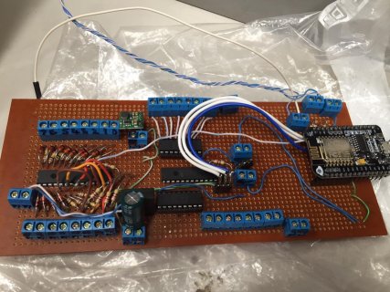
Just thought I'd update that an 11V Zenor diode and 100k resistor did the job with mcp23017 inputs.
Ignore that esp8266. It's getting replaced with a teensy and wiz5100 i swear.
Image-1.jpg
 
Status
Not open for further replies.
Back
Top