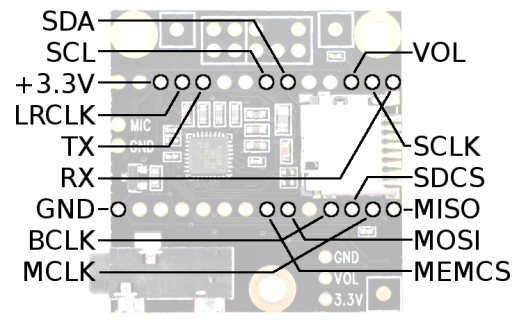
what is Audio Module Pin Mapping

Status
Not open for further replies.

Balam

Active member
HI
teensy newbeee here, but hungry for learning.

I have a teensy audio module and like to know what pins and how ( pin mapping ) uses the audio pin from the teensy board.

2 reason to know
1- need add pushbuttons
2- solder female header to the audiomodule so need to jump wire from teensy to audio module

thanks
 
I made this up a long time ago for Teensy 3.2. I think it is accurate. It includes the pins for the memory expansion board so you can also free up 2,3 and 4 if you don't use it. Also the volume pot pin 15 can be freed up.

Code:
//         Teensy 3.2 with Audio Adaptor and Memory Expansion and volume pot
//
// These are the pin resources used
//   Memory Expansion board uses:
//      Pins 2,3,4 for chip selects, Pins 7(SI),12(SO),14(SCK)
//   Audio Adaptor board uses:
//      Pins 7(DI), 10(CS), 12(DO), 14(SCLK) for SD card SPI
//      Pins 18(SDA), 19(SCL), 11(MCLK), 9(BCLK), 23(LRCLK), 22(TX), 13(RX) for SGTL5000 I2S and SPI
//      Pins 15(A1) for 25kohm volume pot. (careful this could be at GND or 3.3V level)
//
//   9 Pins are left over (unless soldering to the underside of the teensy):
//      Pins 0(touch), 1(touch), 5, 6, 8, 16(A2,touch), 17(A3,touch), 20(A6), 21(A7)
//      18, 19 are used for the i2c bus and can be shared.
//
// I2S is "Inter-IC Sound" a serial audio bus standard
// SPI is "Serial Peripheral Interface" bus transfers data with SD card and controls the SGTL5000
 
much thanks
looking at the audio webpage image
looks like Pin 13 ( LED ) on teensy = rx ?
teensy3_audio_pins.png
 
Status
Not open for further replies.
Back
Top