
Epyon
Well-known member
Not really a Teensy-specific question, but I'm hoping some of the electronic guys here can help me out ") .
.
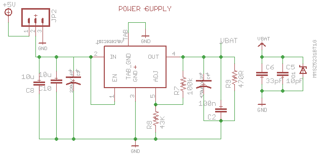
I need to design a power supply circuit for a wireless modem that draws spikes up to 2A for around 600µs while transmitting, with 4ms between consecutive spikes. The voltage drop during these spikes must be less than 350mV. A transmission window can last for around 20s. The output voltage is 3.8V, regulated down from 5V with a MIC29302 LDO.
My 5V line can only deliver 1A max, with around 200mA reserved for Teensy 3.2 and some peripherals. So I'm planning to provide enough buffer capacitance to provide the peak current. 470µF at the output, 220µF at the input of the LDO.
I found a reference circuit for this that recommends using tantalum capacitors, the primary reason being their low ESR of course. When I looked up the ESR of modern electrolytic capacitors however, it struck me that their ESR is in the same range! E.g. the 470µF tantalum AVX TPME477K006R0018 has a ESR of 18mOhm (at 100kHz), the 470µF electrolytic Kemet A765KH477M0JLAE016 has 16mOhm (both rated at 6.3V). They have the same ripple current (around 3A). The tantalum does have a significant lower leakage current of 28µA compared to 592µA of the electrolytic, but for this application this doesn't matter much. The tantalum capacitor does cost more than 10 times the electrolytic one though!
So except for their smaller size and longer (and more stable) lifetime, are there any reasons left to choose tantalum these days? I have more than enough PCB real estate to place electrolytic caps and some ceramic decoupling caps (should prevent ripple current from flowing through and heating the electrolytic cap), and my application won't be operating outside room temperatures (so I should get reasonable lifetime).
.I need to design a power supply circuit for a wireless modem that draws spikes up to 2A for around 600µs while transmitting, with 4ms between consecutive spikes. The voltage drop during these spikes must be less than 350mV. A transmission window can last for around 20s. The output voltage is 3.8V, regulated down from 5V with a MIC29302 LDO.
My 5V line can only deliver 1A max, with around 200mA reserved for Teensy 3.2 and some peripherals. So I'm planning to provide enough buffer capacitance to provide the peak current. 470µF at the output, 220µF at the input of the LDO.
I found a reference circuit for this that recommends using tantalum capacitors, the primary reason being their low ESR of course. When I looked up the ESR of modern electrolytic capacitors however, it struck me that their ESR is in the same range! E.g. the 470µF tantalum AVX TPME477K006R0018 has a ESR of 18mOhm (at 100kHz), the 470µF electrolytic Kemet A765KH477M0JLAE016 has 16mOhm (both rated at 6.3V). They have the same ripple current (around 3A). The tantalum does have a significant lower leakage current of 28µA compared to 592µA of the electrolytic, but for this application this doesn't matter much. The tantalum capacitor does cost more than 10 times the electrolytic one though!
So except for their smaller size and longer (and more stable) lifetime, are there any reasons left to choose tantalum these days? I have more than enough PCB real estate to place electrolytic caps and some ceramic decoupling caps (should prevent ripple current from flowing through and heating the electrolytic cap), and my application won't be operating outside room temperatures (so I should get reasonable lifetime).