College Project using Teensy

Status
Not open for further replies.

wof5051

Active member
Hello everybody, I am new to this thread, as well as I have just started to look into the Teensy as my microcontroller for my project. I am considering the newest one for use. My project is a 4000 LED matrix comprised of Adafruit LED strips. I would like to display pictures and videos on the LED matrix, as well as play audio with my microcontroller. I have the following questions

1.) Will the Teensy with use of an SD card store and play videos and pictures on my LED matrix, as well as output MP3 file music to speakers? We are planning on using desktop computer speakers with an auxiliary jack. Also would it be possible to use these speakers?
2.) What is the quality of the audio that is outputted by the Teensy? '
3.) What program is used to do the coding for the Teensy?

Like I said before, I have no real experience with the Teensy, the only exposure I have to it is a few YouTube videos!

Please anyone and everyone with expertise with the Teensy, if you would send some knowledge my way!! Anyone who has answers or even other ideas and suggestions I am open to anything and very willing to listen and learn!!

Thank you!!!!
 
In general, you want to go through things in steps, rather than trying to do all 4,000 leds at a time.

In terms of LEDs, you want to look at the octows2811 adapter (http://www.pjrc.com/store/octo28_adaptor.html). You need to be careful about power supplies and getting everything soldered down properly.

In 2014, the folk at PJRC made a 4,320 LED video display with the Teensy 3.1 (the 3.2 is a minor upgrade of the 3.1). https://www.community.arm.com/iot/e...l-at-maker-faire-2014-concept-and-development

Note, that it took the 3 of them 3 weeks to assemble all of the LEDs. Also note, one of the examples plays from a SD card with the octows2811.

Now, I am a software guy, but I suspect the Teensy 3.2 probably runs out of gas if you are trying to do a large LED display and do audio at the same time. It probably would be simpler to have two Teensys, one to do the light show, and the other to do the music, and you would have simple commands between the two to sync things up. If you use Neopixels (ws2812) LEDs, the timing to the LEDS is fixed (this allows the LED chain to be a single wire instead of a data and clock wire like the dotstar/APA102 leds use). The upshot of the timing being fixed, is a faster processor (like the Teensy 3.5/3.6) might not speed things up, since the fixed unit is the time between sending out the LED commands is rather strict.

For the audio Teensy, you probably want to use the Audio shield (http://www.pjrc.com/store/teensy3_audio.html). Note, the octows211 and audio shields use some of the same pins, so it is better to split things up to do different tasks.

Before going full hog, get a Teensy 3.2 (or 3.5/3.6, not an LC) and write some simple programs. The code used is basically the Arduino libraries adapted for the Teensy, which is a simplified C++ underneath the covers. This way you can see whether you can get comfortable doing the work. First get a Teensy or two. Then get an Octows2811 shield and play with this on short ws2812/neopixel LEDs (say 8 of these neopixel sticks: https://www.adafruit.com/products/1426). The octows2811 does things in 8 parallel strands, so you want to do stuff that incorporates all 8 LED strands, without jumping in to buy 4,000 LEDs all at once.

Then get a second Teeensy and the audio shield, and play around with that.

Then you can start working on the big unit.

However, you should also start learning how to dive into web sites, to figure out things like what is the programming system like.
 
Last edited:
A couple years ago we built a project very similar to what you're describing. I see Michael already mentioned it, but here's the link again. I wrote a pretty detailed description of how it worked and how it was built. There's even a 1 minute video so you can see it in action.

https://www.community.arm.com/iot/e...l-at-maker-faire-2014-concept-and-development

The audio and video were written into a single file on the SD card, using a sketch in Processing to convert the video, and then a C program to merge in the audio data. You can find those programs here:

https://github.com/PaulStoffregen/OctoWS2811/tree/master/extras/VideoSDcard

This audio output was mono using the 12 bit DAC, fed right into amplified computer speakers. It sounded pretty good, but of course those specs aren't going to impress any audiophiles.
 
Is there a touchscreen interface or something we can use...or how would you all suggest controlling what is on the display?
 
Paul,
what gauge wire is used in that LED video board? I have 6 gauge for connecting to the power supplies, and I am assuming to use something like 12 to connect the LEDs to one another. Any insight on this would be greatly appreciated, thank you!
 
what gauge wire is used in that LED video board?

We used 20 gauge wire, approx 1.5 feet long, on both ends of every 90-LED strip.

If you keep the wires short and run dedicated wires directly from each strip back to the power supplies, 22 gauge is also perfectly acceptable. I do not recommend going to 24 or smaller.

Since this is an academic project, and for your own personal learning experience, I'd recommend measuring the actual resistance of the wires you use. Odds are good your instructor will love this sort of info in whatever writeup you end up submitting. If you have access to fancy bench-top power supplies with 4-wire resistance measurement, use that. If you don't have such fancy gear, get a 10 ohm 1% resistor rated for 5 or more watts. Digikey and other places have them. Connect your power supply to the resistor, using the wires. Then measure the voltage on the resistor and use ohm's law to get the actual current. Then use the mV mode on your multimeter to measure the voltage drop on the two wires. Thing of them as small resistors, not wires, so you've got 3 resistors in series. Of course, those will be in series when you connect to the LED strips, and the one in series between the GND on the LED strip and GND on power supply will cause the LED strip's GND to be as slightly (or perhaps not so slightly) different voltage than other stuff connected directly to the power supply GND. Again, useful stuff for your academic writeup.....
 
Last edited:
We used 20 gauge wire, approx 1.5 feet long, on both ends of every 90-LED strip.

If you keep the wires short and run dedicated wires directly from each strip back to the power supplies, 22 gauge is also perfectly acceptable. I do not recommend going to 24 or smaller.

Since this is an academic project, and for your own personal learning experience, I'd recommend measuring the actual resistance of the wires you use. Odds are good your instructor will love this sort of info in whatever writeup you end up submitting. If you have access to fancy bench-top power supplies with 4-wire resistance measurement, use that. If you don't have such fancy gear, get a 10 ohm 1% resistor rated for 5 or more watts. Digikey and other places have them. Connect your power supply to the resistor, using the wires. Then measure the voltage on the resistor and use ohm's law to get the actual current. Then use the mV mode on your multimeter to measure the voltage drop on the two wires. Thing of them as small resistors, not wires, so you've got 3 resistors in series. Of course, those will be in series when you connect to the LED strips, and the one in series between the GND on the LED strip and GND on power supply will cause the LED strip's GND to be as slightly (or perhaps not so slightly) different voltage than other stuff connected directly to the power supply GND. Again, useful stuff for your academic writeup.....

Perfect thank you and I agree I will test that and include in the report


Just to clarify, the OctoWS2811 and the audio add-on are both compatible with the Teensy 3.6 Correct? Or would you suggest using the 3.2 for this project instead of the 3.6?

Thanks for answering all my questions!
 
Perfect thank you and I agree I will test that and include in the report


Just to clarify, the OctoWS2811 and the audio add-on are both compatible with the Teensy 3.6 Correct? Or would you suggest using the 3.2 for this project instead of the 3.6?

Thanks for answering all my questions!

Just wanted to confirm this before I order, that the OctoWS2811 and audio shield will work with the 3.6? I couldn't seem to find an answer for this elsewhere. Thank you
 
Yes, OctoWS2811 works on Teensy 3.6.

If using the $10 octo board, you'll need long pins and sockets to get the Teensy 3.6 positioned high enough, since it's longer than Teensy 3.2 and overhangs the end.
 
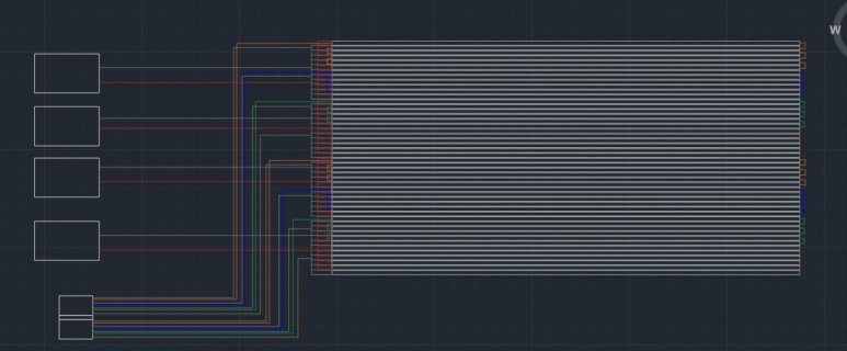
So I made up what I think should be the wiring diagram...Does this correct? Red obviously power, ground is the grey, and the colored are the different data lines from the Ethernet. I know that the power requirements are correct as far as amperage/voltage from the power supplies, just checking that my wires look right. Thank you

Wiring diagram.jpg
 
After reading over your write-up of your video panel, it has come to my attention that I need to run power and ground to each end of the LED strips. If I am reading this correctly?
 
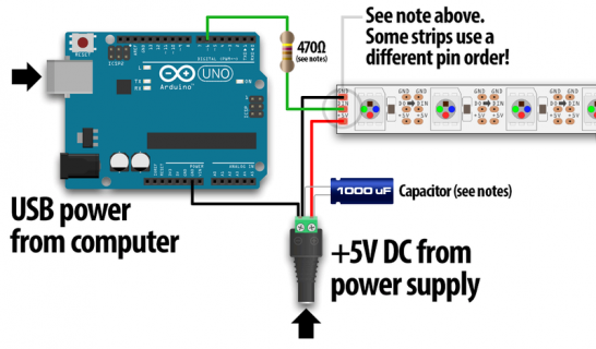
cap and res.png

Also, the LED manufacturer offers this advice and I was wondering what your opinion on this was...

"When using a DC power supply, or an especially large battery, we recommend adding a large capacitor (1000 µF, 6.3V or higher) across the + and – terminals. This prevents the initial onrush of current from damaging the pixels. See the photo on the next page for an example."

"Adding a ~470 ohm resistor between your microcontroller's data pin and the data input on the NeoPixels can help prevent spikes on the data line that can damage your first pixel. Please add one between your micro and NeoPixels! Our NeoPixel rings already have this resistor on there"
 
All of your above questions are good best practise, but you may be able to get away without doing so. If you can, especially for a project that will be in use for a long time do them all, and then do some measurements to make sure they actually work as expected. If this is more of a one off and you can afford for it to fail at some future point weigh up your risks.

The series resistor is generally easy to do, and believe the Octo board was them already and does double duty protecting your input if strange things happen on the strip and also protects the strip is you drive voltage to it with the strip off.

The powering from both ends depends on the length and strip quality (copper resistance). Powering from one end isn't going to blow them up, but if you get redish tints at the far end (red LEDs stay bright at lower voltages) then you need moar power to the strip.

The Capacitors are harder to add, and going overboard can cause it's own problems with inrush killing your power supply, but if you have problems if high brightness changes causing garbled patterns and crashing then making sure you have caps in line will help. As will keeping your PSU physically close to the strip and the leads a decent size.
 
Using capable power supplies (running at 75% of less of their fully rated capacity) and getting them physically close to the LEDs with power short wires will eliminate most of the need to add a big capacitor close to the LEDs. The power supply already has big caps built in, of course if it's a large one rated for 20A to 50A current.

That 1000 uF capacitor advice from Adafruit and others (many websites just blindly copy whatever Adafruit says) applies mostly in the case where you buy Adafruit's small power supplies with long cords. For a large & high power LED project, small power supplies and long power wires are the absolute worst thing you can do. Just adding a capacitor is a nice quick fix for people who've gotten in slightly over their heads (and the power supply & cord's capability), but it won't save you for a project of this scale.

I know Adafruit's website and tutorials are very compelling, but you really must understand 99% of their NeoPixel business is customers using less than 100 LEDs. For a huge 4000 LED project, you're in a totally different realm. Many of the general "rule of thumb" guidelines on Adafruit's site are only solid advice if you're building relatively small LED projects.


Cool thank you for the response. I am actually using 4, 60 amp power supplies. Been doing a lot of calcs lately. Should I be concerned using 20 gauge wire with this high of amperage? As many wires are going into each power supply my calcs how that I should be fine.

I am using 4, 60 amp power supplies as stated. I have 48 rows of LEDs, with 90 LEDs per row. I am using 1 power supply to control 24 rows and a second to control the bottom 24 on the left side, with an identical setup on the right side
 
First of sorry for all the questions but I am super appreciative that you answer them! You're a class act and I really appreciate you helping me through this.

I was wondering if you could describe to me the connection of the red and the black wires that run from one set of power supplies to the other??
 
Keep getting a particular error when trying to configure my audio system with the Teensy 3.6 and the audio shield...

The error goes as this, and any input would be great. Thank you!

Multiple libraries were found for "SD.h"
Used: C:\Program Files (x86)\Arduino\hardware\teensy\avr\libraries\SD
Not used: C:\Program Files (x86)\Arduino\libraries\SD
Error compiling for board Teensy 3.6
 
Scroll up for the actual error.

You can eliminate that warning by deleting C:\Program Files (x86)\Arduino\libraries\SD. Or simply move that copy of SD somewhere else on your computer where Arduino doesn't look.
 
Well here is the actual error then. Now that I see what it is...I don't have mp3 decoder downloaded....In fact I'm playing around with some of the codes that you suggested to me from Frank and I'm not quite sure which one/ones will work best for me


C:\Users\Wes\Documents\Arduino\audio1\audio1.ino:32:39: fatal error: play_sd_mp3.h: No such file or directory

#include <play_sd_mp3.h> //mp3 decoder

^

compilation terminated.

Multiple libraries were found for "SD.h"
Used: C:\Program Files (x86)\Arduino\hardware\teensy\avr\libraries\SD
Not used: C:\Program Files (x86)\Arduino\libraries\SD
Error compiling for board Teensy 3.6.
 
Status
Not open for further replies.
Back
Top