Hi all,
I'm playing around with Teensy 3.6, attempting to generate a 134kHz sine wave via the DAC. It's working great and I'm now just trying to optimize as much as possible. When I disassemble the .elf, I find that there's a strh+movw instruction per DAC output, and ARM docs note that strh is 2 clock cycles and movw is 1 clock cycle. However, to get 134kHz, I find that I have to send 223 values per wavelength, which is odd because: 180MHz(Teensy speed) / 134kHz(freq) / 223(values) = 6 clock cycles, but my code should only be taking 3 clock cycles, thus my waveform should be twice as fast.
Also, overclocking to 240MHz seems to produce the same speed with no change.
Here's the code:
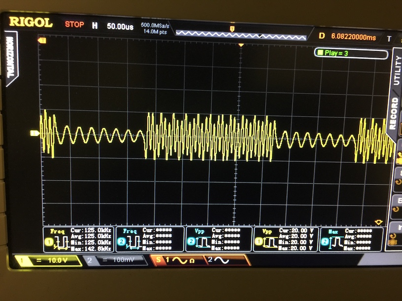
The waveform looks good:

And a section of the disassembly inside the while:

Thanks!
I'm playing around with Teensy 3.6, attempting to generate a 134kHz sine wave via the DAC. It's working great and I'm now just trying to optimize as much as possible. When I disassemble the .elf, I find that there's a strh+movw instruction per DAC output, and ARM docs note that strh is 2 clock cycles and movw is 1 clock cycle. However, to get 134kHz, I find that I have to send 223 values per wavelength, which is odd because: 180MHz(Teensy speed) / 134kHz(freq) / 223(values) = 6 clock cycles, but my code should only be taking 3 clock cycles, thus my waveform should be twice as fast.
Also, overclocking to 240MHz seems to produce the same speed with no change.
Here's the code:
Code:
void setup()
{
  pinMode(13, OUTPUT);
  digitalWrite(13, HIGH);
  analogWriteResolution(12);
  SIM_SCGC2 |= SIM_SCGC2_DAC0;
  DAC0_C0 = DAC_C0_DACEN | DAC_C0_DACRFS; // 3.3V VDDA is DACREF_2

// ensure volatile to prevent optimizations removing code
#define DAC0(a) *(volatile int16_t *)&(DAC0_DAT0L)=a

  // 223 values (per sine) with unrolled loop to get ~134kHz on 180MHz Teensy 3.6
  while (1)
  {
    DAC0(2048); DAC0(2105); DAC0(2163); DAC0(2220); DAC0(2278); DAC0(2335); DAC0(2392); DAC0(2449); DAC0(2505); DAC0(2561); DAC0(2617); DAC0(2672); DAC0(2727); DAC0(2781); DAC0(2834); DAC0(2887); DAC0(2940); DAC0(2991); DAC0(3042); DAC0(3092); DAC0(3141); DAC0(3190); DAC0(3237); DAC0(3283); DAC0(3329); DAC0(3373); DAC0(3417); DAC0(3459); DAC0(3500); DAC0(3540); DAC0(3579); DAC0(3617); DAC0(3653); DAC0(3689); DAC0(3722); DAC0(3755); DAC0(3786); DAC0(3816); DAC0(3844); DAC0(3871); DAC0(3897); DAC0(3921); DAC0(3943); DAC0(3964); DAC0(3984); DAC0(4002); DAC0(4018); DAC0(4033); DAC0(4046); DAC0(4058); DAC0(4068); DAC0(4077); DAC0(4084); DAC0(4089); DAC0(4093); DAC0(4095); DAC0(4095); DAC0(4094); DAC0(4091); DAC0(4086); DAC0(4080); DAC0(4073); DAC0(4063); DAC0(4052); DAC0(4040); DAC0(4026); DAC0(4010); DAC0(3993); DAC0(3974); DAC0(3954); DAC0(3932); DAC0(3909); DAC0(3884); DAC0(3858); DAC0(3830); DAC0(3801); DAC0(3771); DAC0(3739); DAC0(3706); DAC0(3671); DAC0(3635); DAC0(3598); DAC0(3560); DAC0(3521); DAC0(3480); DAC0(3438); DAC0(3395); DAC0(3351); DAC0(3306); DAC0(3260); DAC0(3213); DAC0(3165); DAC0(3117); DAC0(3067); DAC0(3017); DAC0(2965); DAC0(2914); DAC0(2861); DAC0(2808); DAC0(2754); DAC0(2699); DAC0(2644); DAC0(2589); DAC0(2533); DAC0(2477); DAC0(2420); DAC0(2364); DAC0(2306); DAC0(2249); DAC0(2192); DAC0(2134); DAC0(2076); DAC0(2019); DAC0(1961); DAC0(1903); DAC0(1846); DAC0(1789); DAC0(1731); DAC0(1675); DAC0(1618); DAC0(1562); DAC0(1506); DAC0(1451); DAC0(1396); DAC0(1341); DAC0(1287); DAC0(1234); DAC0(1181); DAC0(1130); DAC0(1078); DAC0(1028); DAC0(978); DAC0(930); DAC0(882); DAC0(835); DAC0(789); DAC0(744); DAC0(700); DAC0(657); DAC0(615); DAC0(574); DAC0(535); DAC0(497); DAC0(460); DAC0(424); DAC0(389); DAC0(356); DAC0(324); DAC0(294); DAC0(265); DAC0(237); DAC0(211); DAC0(186); DAC0(163); DAC0(141); DAC0(121); DAC0(102); DAC0(85); DAC0(69); DAC0(55); DAC0(43); DAC0(32); DAC0(22); DAC0(15); DAC0(9); DAC0(4); DAC0(1); DAC0(0); DAC0(0); DAC0(2); DAC0(6); DAC0(11); DAC0(18); DAC0(27); DAC0(37); DAC0(49); DAC0(62); DAC0(77); DAC0(93); DAC0(111); DAC0(131); DAC0(152); DAC0(174); DAC0(198); DAC0(224); DAC0(251); DAC0(279); DAC0(309); DAC0(340); DAC0(373); DAC0(406); DAC0(442); DAC0(478); DAC0(516); DAC0(555); DAC0(595); DAC0(636); DAC0(678); DAC0(722); DAC0(766); DAC0(812); DAC0(858); DAC0(905); DAC0(954); DAC0(1003); DAC0(1053); DAC0(1104); DAC0(1155); DAC0(1208); DAC0(1261); DAC0(1314); DAC0(1368); DAC0(1423); DAC0(1478); DAC0(1534); DAC0(1590); DAC0(1646); DAC0(1703); DAC0(1760); DAC0(1817); DAC0(1875); DAC0(1932); DAC0(1990); DAC0(2048); //DAC0(  2048);DAC0( 2127);DAC0( 2207);DAC0( 2287);DAC0( 2366);DAC0( 2444);DAC0( 2523);DAC0( 2600);DAC0( 2676);DAC0( 2752);DAC0( 2826);DAC0( 2900);DAC0( 2972);DAC0( 3042);DAC0( 3111);DAC0( 3179);DAC0( 3245);DAC0( 3308);DAC0( 3370);DAC0( 3430);DAC0( 3488);DAC0( 3544);DAC0( 3597);DAC0( 3648);DAC0( 3697);DAC0( 3743);DAC0( 3786);DAC0( 3827);DAC0( 3865);DAC0( 3901);DAC0( 3933);DAC0( 3963);DAC0( 3990);DAC0( 4014);DAC0( 4034);DAC0( 4052);DAC0( 4067);DAC0( 4079);DAC0( 4087);DAC0( 4093);DAC0( 4095);DAC0( 4094);DAC0( 4090);DAC0( 4083);DAC0( 4073);DAC0( 4060);DAC0( 4044);DAC0( 4024);DAC0( 4002);DAC0( 3977);DAC0( 3949);DAC0( 3917);DAC0( 3883);DAC0( 3847);DAC0( 3807);DAC0( 3765);DAC0( 3720);DAC0( 3673);DAC0( 3623);DAC0( 3571);DAC0( 3516);DAC0( 3460);DAC0( 3401);DAC0( 3340);DAC0( 3277);DAC0( 3212);DAC0( 3145);DAC0( 3077);DAC0( 3007);DAC0( 2936);DAC0( 2863);DAC0( 2789);DAC0( 2714);DAC0( 2638);DAC0( 2561);DAC0( 2484);DAC0( 2405);DAC0( 2326);DAC0( 2247);DAC0( 2167);DAC0( 2087);DAC0( 2008);DAC0( 1928);DAC0( 1848);DAC0( 1769);DAC0( 1690);DAC0( 1611);DAC0( 1534);DAC0( 1457);DAC0( 1381);DAC0( 1306);DAC0( 1232);DAC0( 1159);DAC0( 1088);DAC0( 1018);DAC0( 950);DAC0( 883);DAC0( 818);DAC0( 755);DAC0( 694);DAC0( 635);DAC0( 579);DAC0( 524);DAC0( 472);DAC0( 422);DAC0( 375);DAC0( 330);DAC0( 288);DAC0( 248);DAC0( 212);DAC0( 178);DAC0( 146);DAC0( 118);DAC0( 93);DAC0( 71);DAC0( 51);DAC0( 35);DAC0( 22);DAC0( 12);DAC0( 5);DAC0( 1);DAC0( 0);DAC0( 2);DAC0( 8);DAC0( 16);DAC0( 28);DAC0( 43);DAC0( 61);DAC0( 81);DAC0( 105);DAC0( 132);DAC0( 162);DAC0( 194);DAC0( 230);DAC0( 268);DAC0( 309);DAC0( 352);DAC0( 398);DAC0( 447);DAC0( 498);DAC0( 551);DAC0( 607);DAC0( 665);DAC0( 725);DAC0( 787);DAC0( 850);DAC0( 916);DAC0( 984);DAC0( 1053);DAC0( 1123);DAC0( 1195);DAC0( 1269);DAC0( 1343);DAC0( 1419);DAC0( 1495);DAC0( 1572);DAC0( 1651);DAC0( 1729);DAC0( 1808);DAC0( 1888);DAC0( 1968);DAC0( 2048);  }
  }
}

void loop() { }
The waveform looks good:
And a section of the disassembly inside the while:
Thanks!