Hi again, I'm coming from another post but since I've characterized the problem I though it was better to clearly write here again all details to see if we can find the reason of the error.
I'm trying to read through serial with Teensy 3.6 mounted with WIZ820io & Micro SD Card Adaptor (MASTER) the data coming from a Teensy 3.6 without any board mounted (SLAVE). When doing Serial1.available() return value is always 0 and Serial1.read() is -1.
Current mounting on protoboard is the one shown below, where GND pins are connected together and RX1 on pin 0 of the MASTER is connected into TX1 on pin 1 of the Slave.
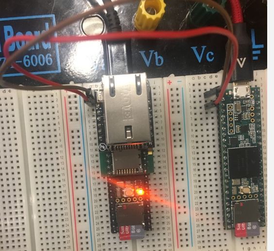
USB cables are coming from 2 different laptops, and protoboard continuity has been checked.
/////MASTER RECEIVER CODE (LEFT BOARD)
/////////SLAVE SENDER CODE (RIGHT BOARD)
Other things that have been tried:
- Successful writing from MASTER to SLAVE (TX1 from MASTER connected to RX1 of SLAVE)
- Successful reading and writing using any other Serial Ports but 1 on both SLAVE and MASTER.
- Different baudrates.
- Same power supply for both MASTER and SLAVE.
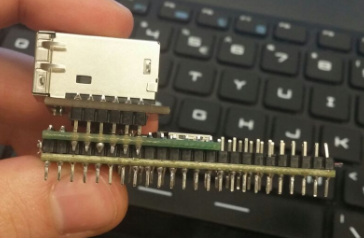
- Checked continuity for header MASTER soldering.
- Checked WIZ820io and SD card pinout (https://www.pjrc.com/store/wiz820_sd_adaptor.html) It's supposed that pins 0 and 1 are not connected to anything, they are just through holes within the adapter, so that shouldn't interfere.
The only conclusion I can have is RX1 doesn't work in the board mounted with the MASTER WIZ820io and SD card adaptor. I can't change my current configuration since the PCB is already printed and need to figure out a solution. Timing is not good for the project, so it's kinda urgent.
Thank you so much for your help and let me know any doubt.
I'm trying to read through serial with Teensy 3.6 mounted with WIZ820io & Micro SD Card Adaptor (MASTER) the data coming from a Teensy 3.6 without any board mounted (SLAVE). When doing Serial1.available() return value is always 0 and Serial1.read() is -1.
Current mounting on protoboard is the one shown below, where GND pins are connected together and RX1 on pin 0 of the MASTER is connected into TX1 on pin 1 of the Slave.
USB cables are coming from 2 different laptops, and protoboard continuity has been checked.
/////MASTER RECEIVER CODE (LEFT BOARD)
Code:
unsigned long prev = 0;
char c;

void setup() {

Serial.begin(9600);
 Serial1.begin(9600);
 pinMode(13, OUTPUT);
 digitalWrite(13, HIGH);

}

void loop() {

if(millis() - prev>100){
  Serial.println("1");
  prev = millis();
 }

while(Serial1.available()){
   c = Serial1.read();
   Serial.print(c);
 }

}
/////////SLAVE SENDER CODE (RIGHT BOARD)
Code:
void setup() {

  Serial.begin(9600);
  Serial1.begin(9600);

}

void loop() {

  Serial1.println("Hi Master");
  Serial.println("Printing");

  delay(100);

}
Other things that have been tried:
- Successful writing from MASTER to SLAVE (TX1 from MASTER connected to RX1 of SLAVE)
- Successful reading and writing using any other Serial Ports but 1 on both SLAVE and MASTER.
- Different baudrates.
- Same power supply for both MASTER and SLAVE.
- Checked continuity for header MASTER soldering.
- Checked WIZ820io and SD card pinout (https://www.pjrc.com/store/wiz820_sd_adaptor.html) It's supposed that pins 0 and 1 are not connected to anything, they are just through holes within the adapter, so that shouldn't interfere.
The only conclusion I can have is RX1 doesn't work in the board mounted with the MASTER WIZ820io and SD card adaptor. I can't change my current configuration since the PCB is already printed and need to figure out a solution. Timing is not good for the project, so it's kinda urgent.
Thank you so much for your help and let me know any doubt.
Last edited: