Audio + RA8875 - SPI?

Status
Not open for further replies.

MaHa76

Active member
Hello together,

I am working on a little Audio-Player for my daugther. I am using Teensy 3.2 + Audio and TFT with RA8875.

Teensy is working very well with TFT and library from Sumotoy. But I have some problems when I am trying ton start some Audio- functions. I have found that page regarding SPI problems on RA8875: https://github.com/sumotoy/RA8875/wiki/Fix-compatibility-with-other-SPI-devices

Ok, it is easy to add that IC- have allready bougth 10pc.

But now I have also found that "solution" : https://github.com/sumotoy/RA8875/wiki/EastRising-and-Buydisplay-SPI-configuration-and-wiring

Do I have to follow both instruction to make work?
 
No. Personally I wouldn't advise the later solution. I'm not familiar with the exact display it talks about, but it sounds like there is a good chance of damaging it.

What are you using for your audio? and what do you want to do with audio exactly? receive audio samples or just send them?
 
Thank you very much for your answer. I am using the teensy audio board. I would like to play music from SD Card an radio from TEA5767 modul connected to line in.
 
Ok, so I don't think you have to worry about the MISO issue that you've found. That would only be a problem if you want to read from two SPI devices, if one of them is RA8875. From what you've said, you only have one device using SPI, the RA8875.

I think the problem you haven't perhaps realised is that you have contention over pin 11. This is used by the audio board as MCLK, so you cant also use it as SPI MOSI.

Perhaps look into connecting the RA8875 via SPI1 rather than SPI0. Maybe someone who is familiar with Sumotoy's libs can chip in here and say if it supports that?
 
Thanks for that hints. I have used PINs 7 and 14 for tft.
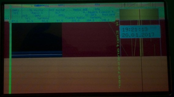
And inserting a sd card is leading to strange drawingings on tft... without any code, only libraries included... what could be the reason for that failure?
When I am adding some sample code for audio functions tft is getting also problems. Sometimes blackscreen on startet, sometimes strange drawing.
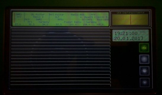
Without any audio functions display is working very nice.
 
As I say, I'm not familiar with the workings of the libraries as I dont use them, but my guess would be that they are hardcoded to use certain pins. I think if you are using two or more libraries that conflict over some pins, you would expect to see odd effects.

E.g. if the audio library takes control of the I2S pins, but you've got some of them wired to the display driver, it only takes the CS to be asserted momentarily with nonsense signals on its SPI lines for it to think you've sent it commands to draw rubbish on the display.

Go back to the signal mux chapter of the micro manual, and work out how to connect all of your devices to dedicated peripherals. Then work out how to get the libs to use the peripherals you've chosen on the pins you've chosen.
 
Time ago I've had the same problem but with ST7735.
Fixed like this:

Code:
[FONT=fixedsys]#define TFT_CS      21
#define TFT_DC      20
#define TFT_RST     3
#define TFT_MOSI    7
#define TFT_SCLK    14
ST7735_t3 tft = ST7735_t3(TFT_CS, TFT_DC, TFT_MOSI, TFT_SCLK, TFT_RST);
AudioControlSGTL5000     audioShield;  

setup(){
    SPI.setMOSI(7);
    SPI.setSCK(14);
    tft.initR(INITR_BLACKTAB);
    audioShield.enable();
}[/FONT]

The point is you need to initialise the RA8875 library after setting the alternate SPI pins and inside setup() or loop().
Some libraries do not have a separate function to initialise and do all in the constructor (I don't know if this is the case with RA8875).
You usually declare the object global, outside setup() and loop();
That was the problem with the old ST7735 library. I have to use the sumotoy library instead the Adafruit library that come with Teensyduino at that time because at that time the constructor was the initialiser.

Hope it helps.
Luis M. Ruiz.
 
OK, thank you very much for your help...

to make sure, that my understanding is right- libraries are inculded and setup is done in that way:

Code:
#include <SPI.h>
#include <RA8875.h>
#include <SD.h>
#include <Encoder.h>
#include <Bounce2.h>
#include <Wire.h>
#include <SerialFlash.h>
#include <Audio.h>
#include <TimeLib.h>
#include <EEPROM.h>

#define RA8875_CS 9
#define RA8875_RESET 20
#define RA8875_MOSI 7
#define RA8875_SCLK 14
#define RA8875_MISO 8
#define SD_DEC     29 //in

RA8875 tft = RA8875(RA8875_CS,RA8875_RESET,RA8875_MOSI,RA8875_SCLK,RA8875_MISO);//Teensy using alternative SPI pin + alt miso

AudioInputI2S            i2s1;           //xy=200,69
AudioOutputI2S           i2s2;           //xy=365,94
AudioConnection          patchCord1(i2s1, 0, i2s2, 0);
AudioConnection          patchCord2(i2s1, 1, i2s2, 1);
AudioControlSGTL5000     sgtl5000_1;     //xy=302,184
const int myInput = AUDIO_INPUT_LINEIN;


void setup() 
{
  Serial.begin(115200);
  Serial.println("RA8875 start");
  
  tft.begin(RA8875_800x480);
  tft.setRotation(2);
  tft.println("starte Annis Radio");
  delay(500);
  tft.fillWindow();
  tft.brightness(DisplayHelligkeit);
  
  AudioMemory(12);
  
  sgtl5000_1.enable();
  sgtl5000_1.inputSelect(myInput);
  sgtl5000_1.volume(0.7);
    
  setSyncProvider(getTeensy3Time);
  Serial.begin(115200);
  
  if ( EEPROM.read(1) == 1 ) { Radio = 1; }
  if ( EEPROM.read(1) == 0 ) { SDMusik = 1; }
  
}

there is a lot more of code and variables defined... but maybe not necessary for that problem (?)
 
Of course you need more includes and code, like the SPI and audio library includes. I've just put the relevant part for the issue with SPI pin remapping.
You just need to add the SPI remapping functions (SPI.setMOSI(), SPI.setMISO(), SPI.setSCK(),...) just before tft.begin(RA8875_800x480);
Make sure that you are using the correct alternate pins.

For instance:
Code:
#define sclk 13  // SCLK can also use pin 14
#define mosi 11  // MOSI can also use pin 7
#define cs   10  // CS & DC can use pins 2, 6, 9, 10, 15, 20, 21, 22, 23
#define dc   9   //  but certain pairs must NOT be used: 2+10, 6+9, 20+23, 21+22
#define rst  8   // RST can use any pin
#define sdcs 4 // CS for SD card, can use any pin

Taken from Paul's github: https://github.com/PaulStoffregen/A...s/spitftbitmap_rotate/spitftbitmap_rotate.ino
It's not specific of ST7735 library, but a common hardware constrain for every library that make use of teensy hardware SPI transfers.
So after you choose the correct alternate pins (those that collide with Audio Shield pins) and being sure they don't use any of the forbidden combinations ( 2+10, 6+9, 20+23, 21+22), you just have to remap that pins (SPI.setMOSI(), SPI.setMISO(), SPI.setSCK(),...) in the setup() before call tft.begin(RA8875_800x480);

Hope it's understandable... it's Friday and I'm a little fuzzy right now XD.
Luis M. Ruiz
 
IMG_20170120_192649.jpgIMG_20170120_192725.jpgOK... so have found that audio board is using PIN14 and PIN13... so I need to find an other for SCLK- right?

And PIN 7 and PIN 11 are also used by audio- board... :-(

So wich PINs can also be used for MOSI and SLCK?

attached 1 pic where you can see display w/o SD Card inserted, and 1 pic with SD Card insert... same Code...
 
Last edited:
Very strange.... I have now played a little bit with CPU- Speed... have now used 72MHz instead of 96MHz... and TFT seams to be OK...

So, I will try to include some Code for Audio and will see what happens.

Would it be better to reduce SPI- Speed? Have found something about that, but have no idea, if it could solve the problem for ever...
 
Pins 6, 7, 10, 12 and 14 are used in the audio shield for SD card slot and memory flash.
If you don't use SD slot and don't have soldered the memory flash you can use those pins as alternate.

Even if you use SD or Flash and depending on how much bandwidth you need for the screen and SD or Flash maybe can share MOSI, MISO, SCK and use other alternate pin for CS.
But if you really need speed for the screen refresh or like your case the screen resolution it's big (800x480), you gonna run out of bandwidth on the SPI bus (48 Mhz clodk I think).

Luis M. Ruiz
 
The audio board uses the following pins:
  • Pin 6 is the CS pin to use if you have soldered a flash memory chip to the audio board (flash is accessed via SPI)
  • Pin 7 is the alternate MOSI pin to access the flash memory chip and/or micro-SD card
  • Pin 9 is the I2S BCLK
  • Pin 10 is the CS pin to use if you want to access the micro-SD card
  • Pin 11 is the I2S MCLK
  • Pin 12 is the standard MISO pin
  • Pin 13 is the I2S RX pin
  • Pin 14/A0 is the alternate SCLK pin
  • Pin 15/A1 is connected to the three pins on the audio shield to install a potentiometer (and it has extra electronics, so it might not be useful for other things if you don't use it as a POT)
  • Pin 18/A4 is the I2C SDA pin (audio board provides pull-up resistors)
  • Pin 19/A5 is the I2C SCL pin (audio board provides pull-up resistors)
  • Pin 22/A8 is the I2S TX pin
  • Pin 23/A9 is the I2S LRCLK pin

So for other SPI devices, you would use pin 7 for MOSI, pin 12 for MISO, pin 14/A0 for SCLK, and you would pick an unused pin for CS. Note, some devices have accelerations if you use the special hardware CS pins. The only hardware CS pins that aren't used by the audio board are pins 20/A7 and 21/A8.

FWIW, I've played around with the Adafruit animated eyes program that drives 2 128x128 displays as fast as possible. I have to downgrade the bus speed to run OLED displays, but the TFT displays I've used, I can run the Teensy 3.6 at its fastest overclock speed. I have to reduce the bus speed to 24Mhz for the Adafruit OLED display and 48Mhz for the New Haven OLED display.
 
Last edited:
OK, that sounds very usefull- I will try to use pin 7 for MOSI, pin 12 for MISO, pin 14/A0 for SCLK.

Speed is not necessary for TFT... I have only a low number of animations... when I am tuning the frequenzy of FM a smal line will be moved, and other "animation" is updating the clock every second... so not so much to do for TFT :)
 
Status
Not open for further replies.
Back
Top