Muitple HD44780 LCD displays

Status
Not open for further replies.

bossredman

Well-known member
Hi,

Been trying to think this through for days now & can't to seem to come up with a definate answer.
SO thought I;d ask here if thats OK?

Is it possible to use a Shift Register to drive the individual Enable pins of multiple HD44780 LCD Char displays?
 
I can do it with a unique I/O pin for each display's ENABLE (all other pins - data & RS can be linked together) - but I'm 2 I/O's short.
I had some Shift registers which I used for LED's - but didnt realise untill earlier today the Enable pin is actually toggled quickly via the LiquidCrystal library.
 
OK will take a look thanks. Not heard or used expanders before so will have to do some reading up.
You think these will work with teh LiquidCrytsal library which when printing anything automatically & briefly flashes/toggles the ENABLE pin high?

I'd previous used 3 x Shift registers to expand my I/O for lighting 24 LED's (3 I/O pins on Teensy for 24 extra pins) so was familiar with those & how to use them - ie "Shiftout" which either sets each of teh 8 bits hi or low.

Just struggling to see how I can get the library to do the toggle.

Make sense?
 
No, the LiquidCrytsal library does not support shift registers in any way.

It is "possible" to do this, but the word "possible" means a lot of work to write an entirely different library. Some people have tried to do this and have published tutorials and libraries. But you find their libraries may not be as well tested and stable as the normal LiquidCrystal library. Here are a few of them:

http://www.electroschematics.com/11155/alphanumeric-lcd-shift-register-arduino-part-1/
https://blog.arduino.cc/2012/01/16/control-an-lcd-with-a-595-shift-register/
http://playground.arduino.cc/Code/LCD3wires

Using the normal LiquidCrystal requires only 6 pins for the minimum setup.

I believe you can use 3 displays with 5 of the 6 signals shared. Only the Enable signal needs to be unique to each display. If you connect this way, only 8 pins should be needed to control 3 displays. Perhaps that is good enough? This way should be "possible" by only connecting wires and using the LiquidCrystal library as it exists now. If you build the shift register hardware, also consider the time and effort needed, including time to troubleshoot if any mistakes are made. Finding mistakes when using shift registers can be much harder than when using simpler wiring.

The other way which already exists uses I2C to communicate with MCP23017 chips that control the displays. Adafruit sells a ready-made board you can use (much easier than building from scratch) and they have a well tested library.

https://www.adafruit.com/products/292
https://github.com/adafruit/Adafruit-MCP23017-Arduino-Library

This way lets you control up to 8 displays using only 2 wires. But something to consider is it can be much slower. Perhaps that's ok?

Of course, so much more is "possible" with a tremendous amount of software and hardware work, including a *lot* of work to troubleshoot problems, which is far more difficult when using shift registers. The question is whether you wish to do so much work?
 
Thanks Paul, that clearly lays things out for me.

Are you able to quantify a little more what "slow" would be for teh "I2C to communicate with MCP23017 chips" solution pls?

I'd have 8 displays (8x2). - each displaying 2 x 5 char words (1 per line) along with a further char per line that may/maynot be displayed.
Updates would only be required after a press of a switch.
 
if your worried about i2c speed, the spi varient runs in the mhz spectrum
for a text lcd it dont really matter
for graphics, speed is of upmost importance
 
I realize you probably have bought the displays and such, but it might be useful to step back and think do you need all of these displays? Could you use a larger display to show everything and just putting the information at different locations on the screen?

I was thinking you could do multiple cheap i2c 16x2 displays, but a lot of the cheap ones have a fixed i2c address. You would need to use something like a TCA9548A I2C Multiplexer to switch each display when you want to update it (or use the multiple 2c buses of the 3.5). Digole.com provides displays where you can set the i2c address at runtime, but those displays start around $10 each. For cheap stuff, bear in mind it is holiday time for Chinese sellers, so you might have to wait until they are back to get shipments. I also note, that many of the cheap displays are listed as 5v only, which is a further complication.
 
8 displays in total.
I was considering S/R's not to save pins exactly, but because I'd run out of i/O pins.

Doh!!! - you know that feeling you can get when the penny finally drops & you feel a total nugget coz the answer was so obvious in the first place?
Well - I got that very feeling about 9:30 am this morning.

For some reason (probably due to my poor soldering skills), I'd totally blanked out of my mind, the I/O ports on the rear face of the Teensy (20 in the case of my Teensy 3.6).
So no need for Shift Registers or GPIO port expanders afterall - just a little practice on my surface soldering technique was all that was required. :)

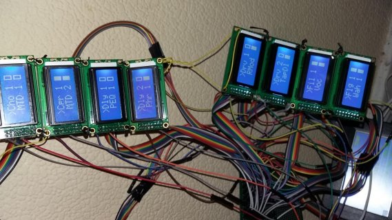
All 8 x LCD displays now working (see photie) - but obviously still in need of mounting & some serious cable management.
But all's good (I hope).

20170125_190555.jpg

Thanks for everyone's help with this.

Cheers
 
be careful soldering a wire directly to the pad, you may pull off the pad. it's safer to solder in a straight header as the support will be better along the board,
 
Talldog over at Tindie has this breakout board for sale that makes it easier to attach and detach connections to the underneath pads of the Teensy 3.5/3.6. He is on this forum also, but I don't remember his screen name. It sounds like your soldering skills are adequate by now. For others that have solder phobia, Talldog will do all of the soldering for you (for a fee).

KurtE and FrankB were also doing breakout boards, but I don't recall if the boards are considered finished or not.
 
it's safer to solder in a straight header as the support will be better along the board,
Talldog over at Tindie has this breakout board for sale that makes it easier to attach and detach connections to the underneath pads of the Teensy 3.5/3.6.

Will bare both these things in mind for future projects - thanks for the info.
 
So.. I managed to get this up and running by re-jigging some of the I/O to use the pads on the rear of the T3.6.

Everything seems to function as expected apart from one occasional glitch.
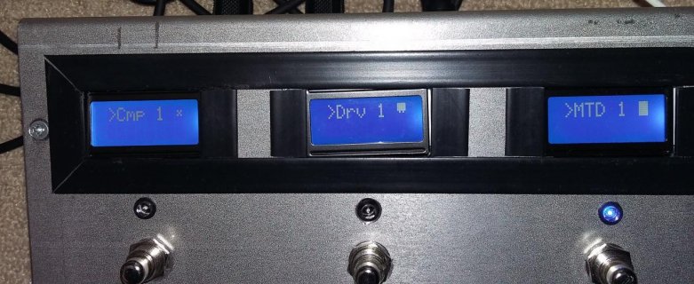
Ref the attached photo - these LCD's display an Effect name and then a 'Special userdefined Char' to show it's current bypass state.
ie a centered 'x' = bypassed (ref LHS LCD) & a filled in rectangle = enabled (ref RHS LCD)
This char is always the last of 8 on each row (2 rows as lcds are 8x2).

Every once in a while this end character appears to become garbled.
See the middle display in the photo
Garbbled End Char.jpg
It looks like its a mixture of teh top half of the filled in rectangle & the bottom half of the centered 'x'.

When updating the char - My code clears the previous value (by printing a space) before writing the new value - so not sure what is causing this.
Toggling teh value will allow the enable (fully rectangle) to display correctly - but not the bypassed 'x'

Code:
if (Disp_FX_Status[n] == 1) 
{ lcd[n].setCursor(7, 0);   lcd[n].print(" ");  lcd[n].setCursor(7, 0);   lcd[n].write(byte(0)); }
else 
{ lcd[n].setCursor(7, 0);   lcd[n].print(" ");  lcd[n].setCursor(7, 0);   lcd[n].write(byte(1)); }

Here's teh custom char code too:

Code:
byte FILL[8] = { 0B11111, 0B11111,  0B11111, 0B11111, 0B11111, 0B11111, 0B11111 };    //Custom char = a Filled Rectangle
byte BLANK[8] = { B00000,  B00000,  B01010,  B00100,  B01010,  B00000,  B00000,  B00000 };   //Custom char =  centered x

 //LCD setup for IA's
      for (int n = 0; n < 8; n++)
      {
          lcd[n].createChar(0, FILL);    lcd[n].createChar(1, BLANK);    lcd[n].begin(8, 2);    lcd[n].clear();
      }

Only way to rectify is to reboot teh Teensy.

Any ideas pls.
 
Sorry, I have not used these type of displays for a long time, so I don't know much to help.

But I wonder why you need to blank the char first before you write it out again. Doesn't the second write update the whole area of the char?

Also wonder if you added a small delay if that would help.. Maybe something like:
Code:
lcd[n].setCursor(7, 0)
delayMicroseconds(100);  // May fudge with this number
if (Disp_FX_Status[n] == 1) 
    lcd[n].write(byte(0)); 
else 
    lcd[n].write(byte(1));

Edit: Should ask/mention: This corruption, does the character show up properly when you boot and then sometimes bad later on, or is it bad at the start? If me, I might also put in delays around the createChar calls to see if this helps...

Again it has been a long time since I used any of these type displays, so not sure if that would help or not. I just remember for some commands you needed
to wait a bit for the display to react.....

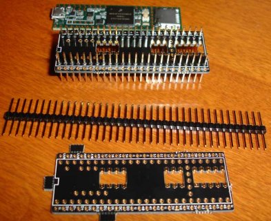
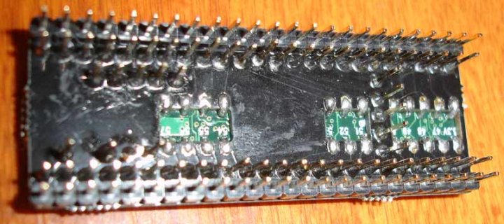
As for easier to solder. I know others have done do.. But I did a quick and dirty adapter board to solder to bottom of T3.5/6 boards. I only soldered one of them so far to at T3.5....

T3.6-castellated-parts.jpg
T3.5-castellated-bottom.jpg

Warning, It was not my best solder job... I mainly use that updated board to do some testing with T3.5
Edit: Note: I believe a copy of the zip file that I sent to OSHPark to make these is up on my github project Teensy 3.1-breakout...
I think the file is: https://github.com/KurtE/Teensy3.1-...nsy-TC36-Breakout/Gerber Chip/Gerber Chip.zip
 
Last edited:
thanks for your comments.

I only recently added the "blank the char first before you write it out again" step to try & eliminate the issue.

At first I thought it had done the trick - but its still happening unfortunately.
 
ANother thing that throws me is - why would this only ever happen to the Last character on each row.

The code that updates this character is part of a routine that when called, updates the whole display for each of teh 8 displays.

Could it be something to do with the fact they are Special Custom Chars possibly?

Code:
void InstanstAccess_LCDs()
{
    for (int n = 0; n <8; n++)
    {
        lcd[n].clear();
        
        //Display 'current' selected IA Effect Bank with a ">".
            if(Effect_Bank_Status == false)
            {
                lcd[n].setCursor(0, 0);   lcd[n].print(">");          lcd[n].setCursor(0, 1);   lcd[n].print(" ");
            }
            else
            {
                lcd[n].setCursor(0, 0);   lcd[n].print(" ");          lcd[n].setCursor(0, 1);   lcd[n].print(">"); 
            }
    
        //Display IA Effect Block Names
            if (Disp_FX[n] != "")
            {
                lcd[n].setCursor(1, 0);   lcd[n].print("        ");   lcd[n].setCursor(1, 0);   lcd[n].print(Disp_FX[n]);
            }
            if (Disp_FX[n + 8] != "")
            {
                lcd[n].setCursor(1, 1);   lcd[n].print("        ");   lcd[n].setCursor(1, 1);   lcd[n].print(Disp_FX[n + 8]);
            }

        //Display each IA Effect Blocks' ByPass State (Byte[0] = FILL = Eff Enabled / Byte[1] = BLANK = Eff ByPassed):
            if (Disp_FX[n] != "")
            {
                if (Disp_FX_Status[n] == 1) 
                  { lcd[n].setCursor(7, 0);   lcd[n].print(" ");  lcd[n].setCursor(7, 0);   lcd[n].write(byte(0)); }
                else 
                  { lcd[n].setCursor(7, 0);   lcd[n].print(" ");  lcd[n].setCursor(7, 0);   lcd[n].write(byte(1)); }
            }

            if (Disp_FX[n + 8] != "")
            {
              if ((Disp_FX_Status[n + 8] == 1) && (Disp_FX[n + 8] != ""))
                { lcd[n].setCursor(7, 1);   lcd[n].print(" ");  lcd[n].setCursor(7, 1);   lcd[n].write(byte(0)); }
              else 
                { lcd[n].setCursor(7, 1);   lcd[n].print(" ");  lcd[n].setCursor(7, 1);   lcd[n].write(byte(1)); }
            }  
    }
}
 
Status
Not open for further replies.
Back
Top