Teensy Microphone Module

Instructions for the Microphone Module - View attachment 11275

Nice work. Lets improve this further more. When selecting required gain or when adjusting AGC enable or disable we have to SOLDER this. What if we want different settings. Can't we put some sort of a micro switch which can switch and select option according to our requirement.
Try to add 2 switches. One to AGC and other one to Gain selection

Why not also an anti aliasing filter and ADC?
Sorry; I'm joking. This board should allow others the try their own design. with the possibilities of OSH park ....
 
Just received my mic order.
Soldered the include pins on the first one, disabled the AGC.
Installed on my controller.
Works like a charm (as expected.
Thanks Neutronned! This makes my solution simpler.
 
Just received my mic order.
Soldered the include pins on the first one, disabled the AGC.
Installed on my controller.
Works like a charm (as expected.
Thanks Neutronned! This makes my solution simpler.

Great! Given that I don't test that on every board, there was a chance that it didn't work. I, like Microsoft, let my customers find the bugs.
 
Adding a switch to select options want affect others. Simply it will help much better

Switches = cost, which is why I didn't add them. I figure you'll configure it once and use it that way forever, so the switches add no value after the initial setting. It would be possible to wire up separate external switches but be careful of noise. Long wires going to sensitive parts of a high-gain amplifier like this one could spell trouble. Good luck!
 
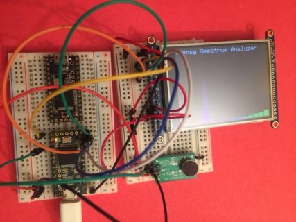
just received my microphone module. spectrum on ILI9341 is working. all is good!
mic.jpg

also tested with adafruit ST7735 TFT LCD 128x160. worked with default SPI clock (15mhz), and worked with 30mhz SPI clock on T3.2@120mhz.

tft.setBitrate(30000000); // needs to follow tft.initR()

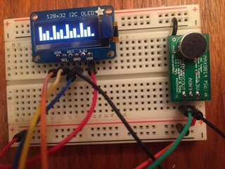
EDIT: and spectrum on 128x32 OLED SSD1306 (16-bar update time: 62 ms, analyzer shows I2C @100khz. TWBR=12 after display.begin, and analyzer shows I2C CLK @333khz and 16-bar update time is 20 ms. if you wanted to get closer to 400khz, use I2C0_F = 0x1a; and update time drops to 16 ms, analyzer shows 395khz). The SPI version (SPI clock 8mhz) 16-bar update time is 890 us, just display() time is 703 us.
oled.jpg
https://www.adafruit.com/product/931
 
Last edited:
just received my microphone module. spectrum on ILI9341 is working. all is good!
View attachment 11292

also tested with adafruit ST7735 TFT LCD 128x160. worked with default SPI clock (15mhz), and worked with 30mhz SPI clock on T3.2@120mhz.

tft.setBitrate(30000000);

Glad to hear that it's working fine. I'll go try that speed-up trick with the SPI clock!
 
mic arrived, works well

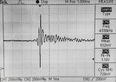
Thanks for the nifty mic board, with two color pages of documentation as well! I haven't actually connected to a Teensy yet, but I see the output bias is right at 0.63 V, and the signal looks good when I flick my fingernail near the mic. In case of interest it draws about 3.5 mA from the 3.3V supply. Looking very carefully at my 6-digit multimeter in averaging mode, I see the current draw actually drops about 1% during louder noises, I suppose due to the AGC action turning down the gain.

NeutronNed-Mic-Snap.jpg
 
Changed the sample code to use tft.drawFastVLine to draw filled boxes - got slightly fast refresh times:

Code:
//****************************************************************************** LCD OUTPUT
    for (byte i = 0; i < 16; i++){   // cycle through the 16 channels

      int line1 = level[i] * 200;
      if (line1 > 200){
        line1 = 200;
      }

      for (byte j = 1; j < 19; j++){  // draw muliple lines to create the bar
        tft.drawFastVLine( i*20 + j, 16, 240-line1, ILI9341_BLACK);
        tft.drawFastVLine( i*20 + j, 240-line1, line1, Wheel565(i * 15 + 60));
      }

    }
  }

  // Teensy 3.6 = 43 to 44msec w/ tft.drawFastVLine
  // Teensy 3.5 = 48 to 49msec w/ tft.drawFastVLine
  // Teensy 3.2 = 59 to 63msec w/ tft.drawFastVLine
  
  //Serial.println(millis() - time);
}
 
I agree, WMXZ.

The mic-->amp signal is minuscule, so noise could easily drown out the signal (low s/n ratio). After the board amplifies the signal, it has a fighting chance to traverse a long wire without noticeable noise.

It would be a nice to be able to stick a mic in a physically-small place.
Your design should take into account having amplification very close to a passive mic.
The Neutronned mic board is comparable in size to SparkFun and Adafruit mic boards (but with the correct bias).

Would there be a noticeable noise increase when the mic would be about 10cm from the microphone module? This is to get the right location is a small tube.
Usage mic - 10-15cm wire - microphone module - about 100cm wire - teensy. and a second microphone module about 20 cm less long in the same tube.
(second module would only be needed to find the direction of specific noise (probably loudness comparing is enough)
 
Hi Neutonmed, I would love to buy one of your MAX9814 mic boards, I've been trying to use the Adafruit one but that DC bias is a killer. :/ However, I'm in Australia, so I just sent a request for postage cost on Tindie. Looking forward to hearing back soon! Thanks!
 
For jpk and endless_harmonics (<cool name BTW), I have added the cost for postage to your countries. It's a shame that the postage is more than the mic!!! If you know of less expensive methods of shipping from US to your country, please let me know!
 
@AlainD, I agree with Neutronned that the setup should work, especially if the electromagnetic environment of the unamplified wire segment is quiet. By what I mean, it the segment is not near oscillating electronics of any kind.

You mention a "tube" that the wire will traverse. Perhaps the tube could be fashioned as a electromagnetic shield of some sort. A grounded wire mesh, perhaps, like you'd see in a Coax cable.

Thanks. The "tube" will almost certain be small PVC and I don't expect much electromagnetic "noise" in the first 10cm.
 
@Neutronned: Thanks! Yes I see that the postage is a bit of a killer. I don't know of cheaper methods as I'm not familiar with USPS options. Just one important question before I potentially order one, do you know if this module
will also be compatible with Teensy LC? Or does Teensy LC have a different internal analog reference voltage?
 
Does Teensy LC have a different internal analog reference voltage?

That is a fine question and one that I can't readily find the answer to! I'm would guess its the same as the Teensy 3.X series given it uses the same Cortex family but maybe Paul or someone that knows can weigh in. I don't actually have an LC or I'd run a quick test.
 
the microphone module looks nice. A couple of questions.

Does the mic sound better than the teensy audio board with a mic connected to the input?
Does it help with power draw spikes when recording to a micro SD card? Have you tried this with recording to a micro SD card?
 
Last edited:
the microphone module looks nice. A couple of questions.

Does the mic sound better than the teensy audio board with a mic connected to the input?
Does it help with power draw spikes when recording to a micro SD card? Have you tried this with recording to a micro SD card?

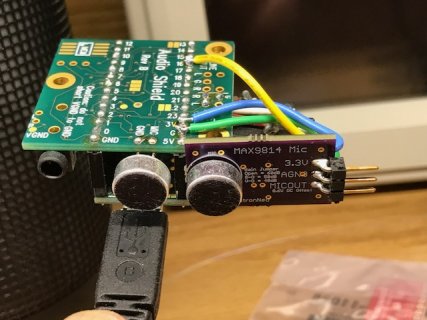
Sound better? I'm not sure I have the equipment to judge this based on accurate measurements but here is my setup and results:
- Teensy 3.2 with Audio board
- microphone element soldered to the Audio Board and tested to confirm pass through to the USB port and Audacity
- one of my analog microphone modules connected to 3.3V, AGND and A2 (16).
IMG_2487.JPG

Here's the code:

Code:
// Teensy 3.2 to stream audio from I2S and analog channel to USB
//  Test microphones are connected to Audio Board mic input and A2
//  Using Audacity to record data

//*********************************************************************************** INIT
#include <Audio.h>
#include <Wire.h>
#include <SPI.h>
#include <SD.h>
#include <SerialFlash.h>

// GUItool: begin automatically generated code
AudioInputAnalog         adc1;           //xy=218,294
AudioInputI2S            i2s1;           //xy=218,337
AudioOutputUSB           usb1;           //xy=422,311
AudioConnection          patchCord1(adc1, 0, usb1, 0);
AudioConnection          patchCord2(i2s1, 0, usb1, 1);
AudioControlSGTL5000     sgtl5000_1;     //xy=226,408
// GUItool: end automatically generated code


//*********************************************************************************** SETUP
void setup() {
  AudioMemory(12);
  sgtl5000_1.enable();
  sgtl5000_1.volume(0.5);
  sgtl5000_1.inputSelect(AUDIO_INPUT_MIC);
  sgtl5000_1.micGain(36);
  delay(1000);
}

//*********************************************************************************** LOOP
void loop() {
}

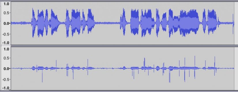
The amplitude from the I2S microphone through the Audio board is lower than the analog mic and there are clicking artifacts on that channel. Are those the power draw spikes you're referencing?? The analog mic sounds fine and natural with no click or anything other than room noise. If I try to increase the gain on the I2S mic by setting the gain higher than around 50, the distortion goes super high. Here is the output from both as recored by Audacity using the original micgain(36) and the default jumpers on the analog mic. Analog mic is the top graph, with the I2S mic from the Audio Shield on the lower graph.
Mic output.jpg

I would say that the analog mic is performing fine but the I2S mic does have more noise. If folks have suggestions on a better test set-up for comparison, please let me know. Happy to perform more testing!
 
Last edited:
In that testing, you aren't using a uSD card. Right? So I imagine these spikes are due to the digitial signals of i2s or something similar. I wonder if you can adapt the recorder.ino sketch to capture from your analog mic directly to uSD card.
I think it's possible to use the 3.5mm input for a mic on the audio board (could be wrong there). I'm curious if the spikes aren't present in that case.

For some of my purposes, I think an analog mic might be better for when I want to place the mic away from the board.

I've been meaning to do some testing but can't find my uSD card, but I ordered another one that'll arrive in a couple of days.
 
I wonder if you can adapt the recorder.ino sketch to capture from your analog mic directly to uSD card.

Using the recorder sketch seems like a straightforward way to check. It looks to be mono not stereo so I won't be able to get side-by-side recordings on the left and right channels, but should be able to get two files - one with the I2S mic and one with the analog mic. I do have a uSD card - just need to wire up the record/stop/play buttons.
 
Okay, I created two "recorder" sketches, one using the adc1 input connected to the analog mic and one with the I2S mic. This obviously means that I can't simultaneously record from both sources but will create two separate .RAW files. Importing these into Audacity and playing them back, I would say the analog mic sounds good - natural and no clipping. The I2S mic sounds a touch compressed and maybe is clipping. Analog on top, I2S mic on the bottom.

Recording test.jpg

Tomorrow I'll try recording some frequency sweeps.
 
Last edited:
Back
Top