Audio board components matching with schematic V2

Status
Not open for further replies.
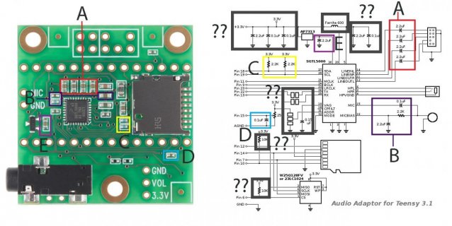
I am trying to figure out components which are in the audio board and matching them with schematic v2. I have figured out some components show in the image. Please help with other components. Please help with the components marked with ?? sign.

Can someone tell what what is the components shown with the red arrow mark (##) sign.

Audio-adaptor-query.jpg
 

Attachments

  • Audio-adaptor-query.jpg
    Audio-adaptor-query.jpg
    118.1 KB · Views: 495
Last edited:
Can someone tell what what is the components shown with the red arrow mark (##) sign.
View attachment 9520

Those represent the configuration pads on the bottom side. They're intended to allow use of a 2nd audio shield, for quad channel. Details here:

https://www.pjrc.com/teensy/gui/?info=AudioInputI2SQuad
https://www.pjrc.com/teensy/gui/?info=AudioOutputI2SQuad
https://www.sparkfun.com/news/2055

The group of 3 lets you reconfigure the I2C address, so the 2nd shield is configurable. The other pairs let you disconnect the RX and TX signals from their normal locations. On the 2nd board, you connect them to the alternate locations, so Teensy is able to receive and transmit the 3rd & 4th audio channels on that board, while it uses the first board normally for channels 1 & 2.

The 0.15 uF capacitor is located immediately to the right of those four 2.2 uF ones (marked "A" in red). To the right of that is the ferrite bead.

The two 10K pullup resistors are near the bottom center of the board, just below the letter "C".


Do you have multiple accounts ?

It's just a coincidence Frank.

I've met Myles in person and I've been to his Cyma Space studio a couple times.
 
Thanks Paul.

I have two more questions. Two 10K pull up resistors one connected to SD card socket and other to CS pin (1) of the flash memory are seen in the schematic. But I am unable to find them in the audio adapter board. They are marked as X in the schematic.

I have marked filter capacitors connected to input pin of AP7313, they are five in numbers 2X (2.2uF) and 3X( 0.1uF). Have I marked them correctly in the picture shown below. One suggestion can't we use one big filter capacitor instead of using so many.

SGTL5000 can work from 3.3 V so then, why we are using AP7313, low drop voltage regulator.

Audio-Q.jpg
 
Two 10K pull up resistors .... unable to find them in the audio adapter board.

Your board is version 1, before those resistors were added. Both schematics on the web page. Scroll down to "Schematic, Version 1".

SGTL5000 can work from 3.3 V...

No, it can't. Table 3 on page 5 of the datasheet says VDDD must be 1.1 to 2.0 volts.


Edit: just to be clear, the photo you originally posted is version 2, which matches this thread's subject. But then you posted a different photo in #4, which is a version 1 board. If you look at the version 2 photo you posted before, you will see it has those 10K resistors. I even mentioned their location in my earlier reply.
 
Last edited:
In the schematic of the audio adapter rev B, it is seen that pin 31 is connected to the pot of 25K, but in the reference diagram pin 31 is connected to GND why?
schematic_audio2.gif

SGTL5000 reference diagram
SGTL5000 reference.png
 
Even if you solder bridge those pads, pin 31 connects to 3.3V. It's only connects to the pot because the pot also happens to connect to 3.3V.

Admittedly, that section of the schematic was a little cramped for space. Things probably would have been visually clearer if I had spent more time to rearrange the whole schematic to make more room, to show the confit pads and the pot with separate 3.3V connections.
 
Paul, according to the schematic, PIN31 is connected (through the jumper) to GND ? A simple solder-bridge (without opening the connection) will short gnd and 3v3 ?
Or am i reading it wrong ? :)
 
Paul, according to the schematic, PIN31 is connected (through the jumper) to GND ? A simple solder-bridge (without opening the connection) will short gnd and 3v3 ?
Or am i reading it wrong ? :)

Correct, if you bridge the open pads without cutting apart the shorted pads, it'll short out the 3.3V power supply. So don't do that.
 
Status
Not open for further replies.
Back
Top