Does anyone have a Teensy Guitar Pedal board?

Status
Not open for further replies.

jwatte

Well-known member
SparkFun has the breadboard-like pedal kit, but that doesn't seem to give any respects to proper ground planes for the low-level instrument signals.

The "Audio Board" has a nice ADC / DAC, but works on "line level" which is > 10x higher voltage than comes out of a guitar.

Anything else out there seems to be made for putting some BJT transistors in and making fuzz.

I can make a board with some op amps and the proper I/O, as well as the necessary robust foot switch and knobs, and even some kind of enclosure. But it'd be so nice if I didn't have to. And if I do, I'd almost certainly end up integrating the ADC/DAC onto that board, rather than having to stack three boards tall just to get where I want to go ...

Yes I have=) Take a look at my site: http://openeffectsproject.com/
It is still a bit beta.. and I am waiting for an upgraded version right now. Tha major change on the new version is that I use the SMD version of the WS2812B (RGB led) instead of the TH. That one is too picky on the voltage supply and I can not make it work in all conditions. They also start by putting blue light on even if I don't send a command to it.
The SMD is good though.

On the website you will not find the jack input/output board yet, but I have them if you like.

What effects do you want to make?
 
I actually followed a link to that site last night, but it never loaded at the time, so I wrote it off as defunct.

It loads this morning :)

Regarding the included hardware, is it instrument or line level?
It's also somewhat unclear from the pictures where the guitar actually plugs in and where the output is.
It says the inputs are on a "separate board" but there's no other board available?
And there's a picture of a board using flat "floppy disk" cable; won't that pick up electrical noise if it's instrument level?
Finally, the picture of the soldered-in Teensy uses the smaller (3.0) form factor Teensy, and there looks to be a header right beside it -- would this still fit the Teensy 3.5/3.6? Does it use 3V or 5V I/O? (the 3.6 isn't 5V tolerant)

Given that the 3.5/3.6 have floating point hardware, I'm thinking of FFT based effects, such as spectral shaping, as well as a convolution reverb. (There's enough RAM for a small amount of reverb, so it'd still have to have some feedback I think, but should be much better than a multi-tap reverb.)

The input buffer in front of the codec is unity gain high impedance input. I did not put any gain there because you can add gain in the codec or Teensy.
I have tried to make a good ground scheme where the "analog" ground is separated from the digital parts. And the ground connections to the jack board are separate to avoid noise/loops.

I have not tested the board with T 3.5/3.6 but the A12 and A13 pin are routed out to the 2pin connector so you can use them with the same pin assignment.

As you said, the pictures and the website is still a bit beta, but I have uploaded better pictures and added the input boards too.
 
The 3.5 and 3.6 are about an inch longer than the 3.2, with correspondingly more holes along the edges. I don't see how that fits the PCB you're currently showing.

Adding digital gain in the Teensy also adds quantization noise, so that's a bad idea. Instrument level is about 300 mV into a megaohm, so id your input impedance is that high, and the codec can be configured to give full scale at 800 mV to 1 V, that would be about right. (You'll want 1 to 2 bits of headroom typically, for unexpectedly hot input playing to not clip)

Another reason I'm cautious about the design of open source pedals is that there are lots of bad designs out there which get even basic things wrong :-(
Look at the article about the Sparkfun pedal board. It claims there is "unexplained" digital grunge. Except they map a 300 mV signal delta into a 9V range, losing almost 5 bits, which would be a good beginning of an explanation...
 
omjanger,
Your openeffects project looks very cool. One question - in the schematic rev 2 the TL072 looks like it is biased at 2.5V and the SGTL5000's VDDA is connected to 1.8V. My son's guitar's humbuckers can output over 0.78V peak when strummed hard. So the lineins can be driven up to 2.5V+0.78V = 3.28V, right? That would violate the codec's absolute max rating analog input of VDDA+0.3V = 2.1V (datasheet page 5). Let me know if I am interpreting this incorrectly or perhaps the schematic has been updated.

Thanks,
SteveC

You are right in that the input from the instrument is biased to 2.5V. That is used instead of using symmetrical positive and negative supply to the opamp. But if we use this solution we must put the caps in front and after the bufferstage to prevent the dc to pass. So it is the same ac voltage swing at the input of the buffer as it is on the output of the buffer. The only difference is the impedance. So this means that C20 and C21 needs to be big enough to carry 20Hz , but block the DC voltage. I put in 10u and that works fine.
 
The 3.5 and 3.6 are about an inch longer than the 3.2, with correspondingly more holes along the edges. I don't see how that fits the PCB you're currently showing.

Adding digital gain in the Teensy also adds quantization noise, so that's a bad idea. Instrument level is about 300 mV into a megaohm, so id your input impedance is that high, and the codec can be configured to give full scale at 800 mV to 1 V, that would be about right. (You'll want 1 to 2 bits of headroom typically, for unexpectedly hot input playing to not clip)

Another reason I'm cautious about the design of open source pedals is that there are lots of bad designs out there which get even basic things wrong :-(
Look at the article about the Sparkfun pedal board. It claims there is "unexplained" digital grunge. Except they map a 300 mV signal delta into a 9V range, losing almost 5 bits, which would be a good beginning of an explanation...

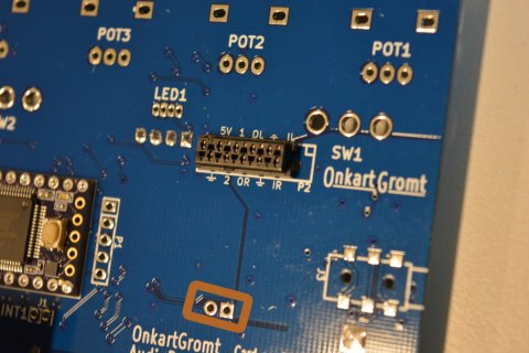
Yes I know that the 3.5 and 3.6 are longer. But I don't use any other extra pins on them than the A12 and A13 that has changed positions. All the other pins have the same positions. You can see those two pins here:
1-DSC_0459.JPG

Regarding the gain is it possible to add analog gain in the codec. 0-22.5dB. That is actual what you are changing when you use the function LineInLevel() in the sgtl5000. That works fine. I have a guitar with levels down in the 100mV and I have an active bass with levels in the 2V range. So to change this is crucial to avoid digital noise. Agree! But in many filter effects you anyway need some headroom if you have some higher Q values in the filters that adds gain.
I also considered to isolate the analog part totally with opto isolators and isolated power. But I ended up with a solution where I carefully laid out the board with respect to ground. So you can see the ground plane is splitted on the picture from SW1, through the black connector and down .
But grounding and laying out a good pcb for analog inputs on the same boards as a lot of other nasty digital noise sources can(and often is) a gradual process. Try and fail and use some good practice... On my new revision I've added an extra 5V regulator to supply the LEDS, relays and the teensy. So the Analog part gets its own regulator.
Sounds good to me, but it will not be a 115dB SNR solution...
 
You are right in that the input from the instrument is biased to 2.5V. That is used instead of using symmetrical positive and negative supply to the opamp. But if we use this solution we must put the caps in front and after the bufferstage to prevent the dc to pass. So it is the same ac voltage swing at the input of the buffer as it is on the output of the buffer. The only difference is the impedance. So this means that C20 and C21 needs to be big enough to carry 20Hz , but block the DC voltage. I put in 10u and that works fine.

That's all good and understood but the problem that I am trying to point out is that it is presenting the SGTL5000 with a voltage over the absolute max spec when VDDA is 1.8V. Violating the max specs may not cause an immediate failure but could affect long term reliability. One solution would be to change VDDA to 3.3V which would allow linein to go up to 3.6V. Also the datasheet suggests a VDDA of 3.3V for best performance. The PJRC audio adapter uses 3.3V.
 
That's all good and understood but the problem that I am trying to point out is that it is presenting the SGTL5000 with a voltage over the absolute max spec when VDDA is 1.8V. Violating the max specs may not cause an immediate failure but could affect long term reliability. One solution would be to change VDDA to 3.3V which would allow linein to go up to 3.6V. Also the datasheet suggests a VDDA of 3.3V for best performance. The PJRC audio adapter uses 3.3V.

Thanks! You are right. It's better to change the Vdda to 3.3V. Will do!
 
This project looks pretty awesome!

Please do make sure the extra length of Teensy 3.6 fits. Later this year (after the USB host stuff) I'm planning to add some pretty awesome effects that will take advantage of the larger memory and faster clock speed.
 
This project looks pretty awesome!

Please do make sure the extra length of Teensy 3.6 fits. Later this year (after the USB host stuff) I'm planning to add some pretty awesome effects that will take advantage of the larger memory and faster clock speed.

Thanks Paul! I am also looking foreward to do more testing with the 3.6. An order for some boards will soon come=)
 
I have the OnkartGromt OpenEffects pedal that is mentioned in this thread. I'm trying to use it with a Teensy 3.6, and the pins I populated in that board fit into the two-pin female header that is populated on the board I have but just shows as holes in the picture of the 02-05-2017 11:11 AM comment. That seems to break the use of the left bat switch associated with A12 (SW1 on the schematic) and connected through J5-2 to pin 31 or 32 on the Teensy. I've tried assigning them all to INPUT using pinMode, but while the right bat switch (A13, SW2, J5-1) still works properly, the left one reads logic high in its left or center position, and resets (probably by shorting) in the right position.
I could remove those two pins from the Teensy board, but I'd rather try to figure out why one switch works and one doesn't.
 
Aaaand, of course, once I wrote about it, I looked more closely at the Teensy 3.6 pinout and realized that the A12 and A13 pins had moved to the main headers and that the underneath pads (for A12 and A13 on the Teensy 3.2) had changed identity. Having removed these incorrect pins, everything works right now.
I have been testing the pedal's IO and functions, and have posted my test program onto my GitHub account <https://github.com/CBMalloch/Arduino/tree/master/OpenEffects_pedal>. Mainly just playing around to familiarize myself with the hardware, but you may find techniques or commentary useful...

Good to hear that you figured it out=)
From your code I see one important improvement:
In your void setup() you should disable the HP filter in the codec. It adds some nasty noise..

sgtl5000_1.adcHighPassFilterDisable();
 
hi,
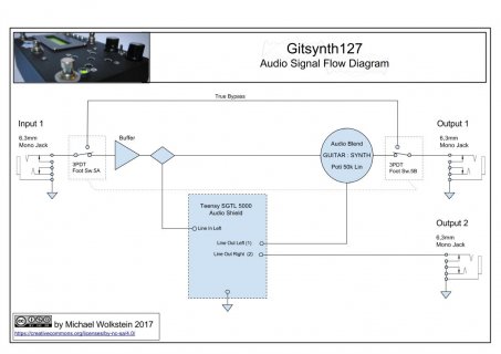
i build an teensy based guitar pedal with the sgtl5000 audio board. i simple use an impendance input buffer based on an mpf102 transistor buffer. The buffer circuit i use is very similar to this one http://www.guitarpcb.com/PDF Files/Buff N Blend.pdf
The nice pro with the blend circuit is that you can blend the amount of digital effect.
The sgtl5000 line-output need no extra buffer or amplifier circuit. You can directly use this signal. I simple return the this in my blend circuit 50k lin poti as shown in the buffn blend documentation.

This is the signal flow diagram from my teensy based guitar pedal board.
Gitsynth127AudioSignalFlow.jpg

my pedal is shown here
https://forum.pjrc.com/threads/4384...with-subtractive-synthesis?highlight=gitsynth

/g
wolke
 
Last edited:
Status
Not open for further replies.
Back
Top