First Project(s) - Midi controllers with 4051 Mux and 595 controlled LEDs

Status
Not open for further replies.

pentium4

Member
Alright, so I'm just getting into the "doing things" phase of my project, and I thought now would be a good time to start a thread to make sure I'm on the right track.
I've done some research so far to at least get a baseline understanding of Teensy and the code I will be using, and have started reading a book on the topic as well.

My plan is essentially two different MIDI controllers; I will build one first, then the other. They are definitely a little ambitious, but I am up for the challenge, and if all goes well I will be well armed with knowledge and parts for future projects.

Midi controller B is my first build; 16 arcade buttons with 5v white LEDs +6 potentiometers (4 knobs, two faders), and I think I can fit 4 more buttons (regular kind,not arcade) for octave +/- and note +/-

Midi Controller A will be second build; 16 knobs (4 are sliders), 4 buttons (banks), and 4 LEDs (bank selection)

I purchased two Teensy 2.0's a little sooner than I should have, but I think they will suit my needs, so long as they can handle the number of '4051 and '595 chips I will be using.

Which is my first question: Model B is planning to have two 74HC4051s and one 74HC595 and Model A is planning to have .... four(?) 74HC4051s (I think... I haven't fully planned that one out yet) - Should I expect any latency/ghosting/general problems with this setup? It seems like the number of chips I'm adding isn't exactly uncommon, but since I am using it for music production, smoothness and accuracy are important.

Second question might be hard to explain: I intend to have the four buttons on Model A swap banks of MIDI CC. That should give me access to 16 faders (4 at a time) and 48 knobs (12 at a time).
This question might be more to do with MIDI than anything, but is there anything special I need to do to make sure when I swap banks that the MIDI mapped knobs do not all jump to the position of the physical knob.
Does that make sense? Most Digital Audio Workstations (DAW) have settings to change how knobs interact with mappings. You can often swap between "pickup" or "latch". Pickup means the value does not change until the knob passes the current value; it then "picks up" the knob at that point. Latch will jump to the knob the moment it is moved.

Let me know if I can provide you guys with anything else. I have zero code really (other than some practice stuff in a text doc).
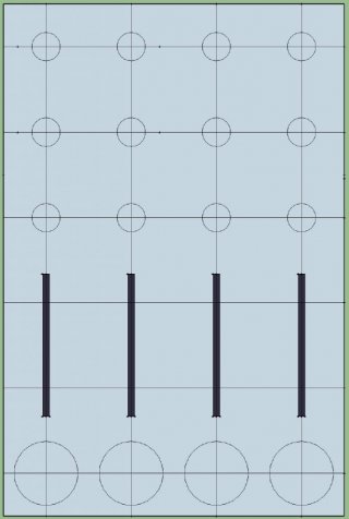
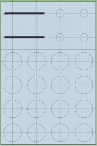
I'll post pictures of my box blueprints. The big circles are arcade buttons, the small ones are knobs, and the black skinny rectangles are faders.
Thanks guys. Love the site, love teensys, love DIY.
 
ModelA.jpgModelB.jpg

Here are the blueprints. Pretty quickly done. I don't know much about CAD, I just wanted something to print that would be 1:1 so I could lay it over my top panels.
 
Which is my first question: Model B is planning to have two 74HC4051s and one 74HC595 and Model A is planning to have .... four(?) 74HC4051s (I think... I haven't fully planned that one out yet) - Should I expect any latency/ghosting/general problems with this setup? It seems like the number of chips I'm adding isn't exactly uncommon, but since I am using it for music production, smoothness and accuracy are important.

No problem, four multiplexers (or more) is not uncommon see Synth-Project.

Second question might be hard to explain: I intend to have the four buttons on Model A swap banks of MIDI CC. That should give me access to 16 faders (4 at a time) and 48 knobs (12 at a time).
This question might be more to do with MIDI than anything, but is there anything special I need to do to make sure when I swap banks that the MIDI mapped knobs do not all jump to the position of the physical knob.
Does that make sense? Most Digital Audio Workstations (DAW) have settings to change how knobs interact with mappings. You can often swap between "pickup" or "latch". Pickup means the value does not change until the knob passes the current value; it then "picks up" the knob at that point. Latch will jump to the knob the moment it is moved.

This is entirely up to you, the behaviour is determined by the software you write. If you don't send any midi data on bank changes nothing will happen at the DAW end.

Kind regards,

Gerrit
 
Which is my first question: Model B is planning to have two 74HC4051s and one 74HC595 and Model A is planning to have .... four(?) 74HC4051s (I think... I haven't fully planned that one out yet) - Should I expect any latency/ghosting/general problems with this setup?

That should be fine.

but is there anything special I need to do to make sure when I swap banks that the MIDI mapped knobs do not all jump to the position of the physical knob.

Maybe. Depending on how you design the rest of the code, you might need to use a variable or some conditional code. It really depends. Ultimately your code is in complete control of what MIDI messages you transmit.

If you're not really familiar with coding, you might save yourself a lot of time and trouble by going with a Teensy++ 2.0 or Teensy 3.5 that has enough pins to connect everything the simplest way. Those boards do cost more. Often people focus on the cost of the chips and then in the end they save maybe $20 on chips, but spend $40 on extra wiring, construction materials, hardware, etc.... not to mention many more hours of difficult work. 10 extra hours to save $20 works out to be $2/hour! If you use the simplest way, then you can use libraries like Bounce and ResponsiveAnalogRead that make everything so much easier on the software side.
 
Thank you both for your replies! I am comforted knowing that my design is at least feasible.

I have indeed realized that perhaps the 2.0 is not the prefect fit for my project; after weighing the shipping costs (and I'm assuming return shipping costs) I decided I would at least give this an attempt on the 2.0. Worst case scenario I burn one out in which case I will gladly buy a set of ++ or 3.5! (This is my tax return gift to myself; as far as tax return presents go, this is a pretty cheap one!)

Paul, are you saying that Bounce library and ResponsiveAnalogRead will not be as easy (or maybe as compatible) with my plan of using muliplex and shif reg, and that have more open pins is the "easier way"?


Separate question: My LED buttons draw 4.8ma at 5v; I will be making a 4x4 matrix to be controlled by the 595. In my head, this means a max draw of (rounded numbers) 5ma x 16 LED = 80 ma.
Will I need resistors for this? Is there already a resistor in this LED? Is that why it is ready for 5v - 12v?
You guys rock. Can't wait for my weekend to start this build.
 
I just ordered some CD74HC4067s so that should free up some pins and let me write code for big chunks of the controller in fewer functions... I think.
*edit for spelling
 
Paul, are you saying that Bounce library and ResponsiveAnalogRead will not be as easy (or maybe as compatible) with my plan of using muliplex and shif reg, and that have more open pins is the "easier way"?

Yes, exactly. Those libs support only directly connected hardware.

And yes, I'm saying the simpler connection without mux and shift register chips is MUCH easier on the software side.
 
Hmm. I might have to rethink some things.
I'm not sure that any of the Teensys have enough I/O for what I want, however, and I think I will have to use the shift register regardless. Hopefully that doesn't get too complicated.
 
Would using the two Teensys for one controller in a master/slave configuration constitute "directly connected hardware"?

It might not be the most cost efficient, but I'm definitely OK with using the two Teensys I have now for Model B and then purchasing maybe the 3.2 for Model A.

But from reading other threads it seems the setup is not so simple; you recommended relegating one Teensy for input and the other for other operations.

I can tell I have more research to do, but I'm convinced with the information available I can make something work.
 
Yes, exactly. Those libs support only directly connected hardware.

As I read that it is saying those libraries need a direct 1 to 1 connection of the pin hardware to the switch or analog signal.

So if the library is running on the Teensy and addressing the pin connected to the end device - not to a multiplexor - then that is directly connected.
 
OK, I slimmed down my original plans and have eliminated all the multiplexing; I have left in one 595 only because the arcade buttons I have look great lit up and it would be a shame to not use them.

Heres the plan so far.

Model A:
8 knobs and 4 faders (12 analog)
4 buttons
4 status LED

Model B:
16 Buttons
4 knobs 2 faders (6 analog)
That should leave 3 pins open for the LED matrix....


Hopefully this will minimize on the complex code required and will let me focus on making a functional controller.
Thanks for all the input!
 
It's always a good idea to try a modest project first to discover your limitations. The physical build can also be harder than you expect too and your first project always looks a bit more amateur than you hoped.

Regarding potentiometer readings for banks of controls:

...is there anything special I need to do to make sure when I swap banks that the MIDI mapped knobs do not all jump to the position of the physical knob.
...Pickup means the value does not change until the knob passes the current value; it then "picks up" the knob at that point. Latch will jump to the knob the moment it is moved.

For 'pick-up' you need to keep track of the last value you sent from that control on that bank and then monitor the difference between the current reading and the stored value.
When the difference value changes signs or gets to within some threshold value from zero you enable MIDI updates.

For 'latched' you need to supress MIDI updates until the current reading is beyond some threshold range from the initial reading obtained after the bank selection event.

For either you'll need to use some variable to keep track of previous values. If you are making a larger controller with this behaviour then you really need to be able to code with arrays.

While there's no reason you would not be able to learn this stuff; if you do not already code C or Arduino there is a bit of a learning curve so it is best to keep the hardware end simple to start.


That said, once you've got the hang of it there is no reason you could not use even the T2.0s to control that number of signals with MUXs.


I was interested to hear about the ResponsiveAnalogRead library... news to me.

It should be great for higher resolution controllers (with course and fine 'bytes') or for super noisy signals as well as giving novices the means to tame pot-noise.

But for 7-bit MIDI CC messages it's usually sufficient to use the extra bits of resolution to limit MIDI-out messages by requiring the signal to pass some difference threshold (which is similar to your 'latch' problem and would likely use similar code!). These methods (search 'hysteresis' and/or 'dead-band') are compatible with MUX'd signals.


MUXed buttons can be de-bouced without the Bounce library using some bit-fiddling tricks to keep track of the pattern of LOW and HIGH bits read on previous passes... because there is time between digital reads as the MUX cycles through each of it's input pins this sequence can mimic the time delay used by Bounce and provide stable output if the frequency of the MUX read is appropriate for the settle time of the switches.

I hope you are successful in your scaled back first project. If you run into trouble and are posting for support remember to post your full code and describe your hardware fully (and photographically or as schematic where appropriate).

The people here are very helpful but are a bit like Parisians... they'll tell you how to get where you want to go but you have to at least try to speak the language! ;)
 
My banks will only be on "Model A", and therefore will be banking 12 pots hopefully with 4 separate banks.

The book I'm reading just got into arrrays, so I will try to make a point to pay close attention to how it is relevant to my project.
I did see another thread where somebody had a similar setup with "previous knob value", but the thread died before he got any response.

When people say "de-bounced" does that have to do with signal noise creating accidental button presses?

I'm building the boxes in the next few days; the one thing I feel fairly confident on!
Although this more direct schematic that I have planned out does seem to be 100x more simple than I had originally thought up.

I'll be sure to share all my pictures and schematics once I get them up.
 
Debounced means 'ignoring chatter as the switch contacts hit and bounce off each other'... microcontrollers are fast enough to read this as multiple events if you don't have some means of ignoring the chatter until it settles down (or that ignores the chatter after picking up the change so as not to fire a second -- while this method would notice the change faster it would also fire in error more easily -- the signal noise case you mentioned)

Bounce takes a time parameter which tells it 'don't declare the state to have changed unless it's changed for at least that long' -- I'm not really sure how and don't really care...

But if you have to figure it out for yourself then you need to track the signal's history

So lets say you poll the pin every so often and it's LOW, then the values are 0,0,0,0,0 ...

Then if there is chatter the bits might look like this when the switch goes from LOW to HIGH:

0,0,0,0,0,0,0,0,0,0,0,0,0,1,0,1,0,0,1,0,1,1,0,1,1,1,1,1,1,1,1,1,1,...

But if you scan for the pattern 0,1,1,1 you will ignore those that don't stay in place for at least three reads and only trigger once as a rising edge .... there are neat tricks to do this efficiently

Don't worry about the details for now... Bounce will sort you out until you really need a MUX.
 
Last edited:
Perfectly clear explanation, thank you for that.

I assume I don't actually have to write out too much code for debouncing. That's the point of the libraries, correct? So that I can copy/paste and then edit in my own values for pins, delay time, etc.


The first step is definitely wrapping my head around as many of these ideas as I can so that I can better plan out my project.
 
https://www.pjrc.com/teensy/td_libs_Bounce.html

Each core library has an instruction page

For Bounce you declare the object in set up... then in your loop you 'read' it and if there is something to read then use the risingEdge/fallingEdge tests to figure out what to do.

If these are triggers (no second message when the button is released) then you only need read the fallingEdge.

Make sure you understand active LOW logic and the use of internal pullups by Teensy.
https://www.pjrc.com/teensy/td_digital.html
 
I've been convinced that the Teensy++ is the best fit for Model B, as it will allow me to wire up each 5v LED directly, as well as each of 16 Arcade buttons and the 6 potentiometers.
The extra Teensy 2.0 I have left over I will save for future projects :)
 
The Teensy 3.5 is 5 volt tolerant on inputs and using a 74HCT part would let you control a 5 volt mux or shift-register with 3.3 volt logic output. But the T++2 will work and will have a single voltage supply.
 
But the T++2 will work and will have a single voltage supply.

Pretty much my reasoning. I've eliminated all need for extra chips or wiring. And I since my LED buttons already have resistors in them, my wiring for this board has gotten extremely simple. Well worth the extra investment.
 
Status
Not open for further replies.
Back
Top