help me for can bus interface using teensy 3.2 and mcp2515 module

Status
Not open for further replies.

Abhijit

Member
hey i am using teensy 3.2 and mcp2515 module to interface with can bus based servo motor drive. for this i found CAN_LIB_MASTER library form github.
In that loopback example is working . but when i send my string on can bus then i got message not send successfully . that mean my string not send on can bus.
i cant understand what is problem. Please help me for this.
 
but when i send my string on can bus then i got message not send successfully . that mean my string not send on can bus.
i cant understand what is problem. Please help me for this.

I'm looking at that library's code right now. It seems to use only the normal SPI library, which works on Teensy 3.2. All other I/O appears to be only the well supported Arduino functions like pinMode, digitalRead, digitalWrite. It really should work.

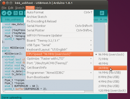
Perhaps this code accesses the MCP2515 too quickly because Teensy is so much faster? As a quick test, try using Tools > CPU Speed to reduce Teensy to only 24 MHz.

If that doesn't help, maybe you could be more specific about "got message not send successfully"? Is this message printing in the Arduino Serial Monitor, or maybe some other way? Perhaps you could give us a screenshot, so we can actually see the message?

Maybe you could be more specific about exactly which of this library's 7 examples you are using? Details matter for solving problems! Please understand we can not see your screen, we can not see your hardware, we can not know what steps you are following.
 
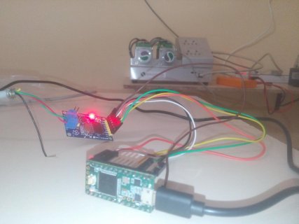
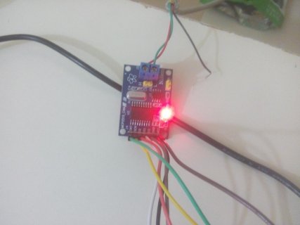
Hey Paul yes i got this message on arduino serial monitor. I am using loopback example in that library in this example I used can in normal mode. And my hardware is teensy 3.2 and mcp 2515 module and servo drive which have can bus communication
 
I do not have this hardware, so the help I can provide is limited, but I am trying. I feel very unaware of what you're doing, as I can't see your screen and you will not even give me a screenshot or the exact text of the error message. This makes helping very difficult.

But I can suggest things like trying 24 MHz mode. Did you do that?
 
Ok I am not doing 24 mhz mode but I will try it n tomorrow I will give you screen shot and exact code which I use
 
hey sorry for late reply this is code which i use:

/* CAN Loopback Example
* This example sends a message once a second and receives that message
* no CAN bus is required. This example will test the functionality
* of the protocol controller, and connections to it.
*
* Written By: Cory J. Fowler - October 5th 2016
*/

#include <mcp_can.h>
#include <SPI.h>

// CAN TX Variables
unsigned long prevTX = 0; // Variable to store last execution time
const unsigned int invlTX = 1000; // One second interval constant
byte data[] = {0xAA, 0x55, 0x01, 0x10, 0xFF, 0x12, 0x34, 0x56}; // Generic CAN data to send

// CAN RX Variables
long unsigned int rxId;
unsigned char len;
unsigned char rxBuf[8];

// Serial Output String Buffer
char msgString[128];

// CAN0 INT and CS
#define CAN0_INT 2 // Set INT to pin 2
MCP_CAN CAN0(10); // Set CS to pin 10


void setup()
{
Serial.begin(115200); // CAN is running at 500,000BPS; 115,200BPS is SLOW, not FAST, thus 9600 is crippling.

// Initialize MCP2515 running at 16MHz with a baudrate of 500kb/s and the masks and filters disabled.
if(CAN0.begin(MCP_ANY, CAN_500KBPS, MCP_16MHZ) == CAN_OK)
Serial.println("MCP2515 Initialized Successfully!");
else
Serial.println("Error Initializing MCP2515...");

// Since we do not set NORMAL mode, we are in loopback mode by default.
CAN0.setMode(MCP_NORMAL);

pinMode(CAN0_INT, INPUT); // Configuring pin for /INT input

Serial.println("MCP2515 Library Loopback Example...");
}

void loop()
{
if(!digitalRead(CAN0_INT)) // If CAN0_INT pin is low, read receive buffer
{
CAN0.readMsgBuf(&rxId, &len, rxBuf); // Read data: len = data length, buf = data byte(s)

if((rxId & 0x80000000) == 0x80000000) // Determine if ID is standard (11 bits) or extended (29 bits)
sprintf(msgString, "Extended ID: 0x%.8lX DLC: %1d Data:", (rxId & 0x1FFFFFFF), len);
else
sprintf(msgString, "Standard ID: 0x%.3lX DLC: %1d Data:", rxId, len);

Serial.print(msgString);

if((rxId & 0x40000000) == 0x40000000){ // Determine if message is a remote request frame.
sprintf(msgString, " REMOTE REQUEST FRAME");
Serial.print(msgString);
} else {
for(byte i = 0; i<len; i++){
sprintf(msgString, " 0x%.2X", rxBuf);
Serial.print(msgString);
}
}

Serial.println();
}

if(millis() - prevTX >= invlTX){ // Send this at a one second interval.
prevTX = millis();
byte sndStat = CAN0.sendMsgBuf(0x100, 8, data);

if(sndStat == CAN_OK)
Serial.println("Message Sent Successfully!");
else
Serial.println("Error Sending Message...");

}
}


in this code i used can in normal mode i.e - CAN0.setMode(MCP_NORMAL);so it avoid loopback. i got message on serial monitor is "Error Sending Message..". an how can i reduce cpu speed to 24mhz . because in arduino IDE in tools there is no option like CPU SPEED. or should i change it from libraries of controller.
 
an how can i reduce cpu speed to 24mhz . because in arduino IDE in tools there is no option like CPU SPEED

Click Tools menu, then click CPU Speed.

24mhz.png
(click image for full size)
 
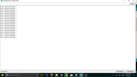
hey i changed the cpu speed to 24mhz but i got same error. this is screenshot:monitor.jpg
and i changed in the code is my can id 0x665,data length - 8 and data is 2B 40 60 00 06 00 00 00
CODE:

#include <mcp_can.h>
#include <SPI.h>

// CAN TX Variables
unsigned long prevTX = 0; // Variable to store last execution time
const unsigned int invlTX = 1000; // One second interval constant
byte data[] = {0x2B, 0x40, 0x60, 0x00, 0x06, 0x00, 0x00, 0x00}; // Generic CAN data to send

// CAN RX Variables
long unsigned int rxId;
unsigned char len;
unsigned char rxBuf[8];

// Serial Output String Buffer
char msgString[128];

// CAN0 INT and CS
#define CAN0_INT 2 // Set INT to pin 2
MCP_CAN CAN0(10); // Set CS to pin 10


void setup()
{
Serial.begin(115200); // CAN is running at 500,000BPS; 115,200BPS is SLOW, not FAST, thus 9600 is crippling.

// Initialize MCP2515 running at 16MHz with a baudrate of 500kb/s and the masks and filters disabled.
if(CAN0.begin(MCP_ANY, CAN_1000KBPS, MCP_16MHZ) == CAN_OK)
Serial.println("MCP2515 Initialized Successfully!");
else
Serial.println("Error Initializing MCP2515...");

// Since we do not set NORMAL mode, we are in loopback mode by default.
CAN0.setMode(MCP_NORMAL);

pinMode(CAN0_INT, INPUT); // Configuring pin for /INT input

Serial.println("MCP2515 Library Loopback Example...");
}

void loop()
{
if(!digitalRead(CAN0_INT)) // If CAN0_INT pin is low, read receive buffer
{
CAN0.readMsgBuf(&rxId, &len, rxBuf); // Read data: len = data length, buf = data byte(s)

if((rxId & 0x80000000) == 0x80000000) // Determine if ID is standard (11 bits) or extended (29 bits)
sprintf(msgString, "Extended ID: 0x%.8lX DLC: %1d Data:", (rxId & 0x1FFFFFFF), len);
else
sprintf(msgString, "Standard ID: 0x%.3lX DLC: %1d Data:", rxId, len);

Serial.print(msgString);

if((rxId & 0x40000000) == 0x40000000){ // Determine if message is a remote request frame.
sprintf(msgString, " REMOTE REQUEST FRAME");
Serial.print(msgString);
} else {
for(byte i = 0; i<len; i++){
sprintf(msgString, " 0x%.2X", rxBuf);
Serial.print(msgString);
}
}

Serial.println();
}

if(millis() - prevTX >= invlTX){ // Send this at a one second interval.
prevTX = millis();
byte sndStat = CAN0.sendMsgBuf(0x665, 8, data);

if(sndStat == CAN_OK)
Serial.println("Message Sent Successfully!");
else
Serial.println("Error Sending Message...");

}
}

/*********************************************************************************************************
END FILE
 
Status
Not open for further replies.
Back
Top