Teensy 3.6 + Audio Shield huge noise

Status
Not open for further replies.
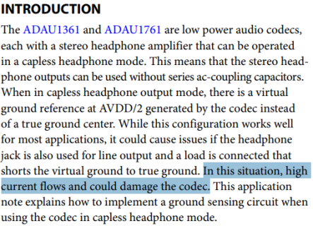
To answer my earlier question why there is this prohibition, a quick google search leads me to another product's application note which says the reason is because a high current between the grounds could damage the codec:

View attachment 22257

Did you experience any damage or degradation to your synth's headphone output sound quality after using your hack of connected VGND to GND?

I took the risk to experiment with this and I guaranty that I do not have any problem by connecting the VGND to GND to my project. The only result was to have clearer sound . The reason that I took the risk was because with that much noise my project was useless . Also as I use this project in a very loud situation (live gigs in a bar) I found that I could hear and other kind of noises like clock sync so I found that I had to short another two pins together (pin 10 + pin 11) to get read also from this kind of noise . In this image you are going to see how I short them together https://imgur.com/ksMECm5 . I am not an expert, however as I described before I had to find a solution immediately as I had to use it in a very loud place, so I do not know what I did exactly however it works perfect with no problems and damages. With this two hacks I manage to have a very silent project that is usable for me . Here is my project that still alive https://imgur.com/h96Blzy
 
ericfont-the attachment method you used didn't work. Would you please possibly include the link to the other product's app note.
Thanks
 
ericfont-the attachment method you used didn't work. Would you please possibly include the link to the other product's app note.
Thanks

Here's the pdf: https://www.analog.com/media/en/technical-documentation/application-notes/AN-1056.pdf

Here's an attempt to re-attach the screenshot:
why-no-short.png
 
Hello Paul . Just yesterday I realised that teensy 3.6 has no connection from shield of headphones output to any ground. That was making a lot of noise for me, when I was trying to listen from headphones while I was transferring audio using usb or line in. I tried to connect the shield from the headphones out to any ground pin to hear the result and fortunately I am so happy to tell that the ground noise disappeared when I attached the cable from headphones shield to GND pin (when I attached the cable from shield to Analoge GND creates an other kind of ground loop noise). I am so happy that I have crystal clear sound with absolutely no noise from 3.6 without buying any ground audio or usb isolator . I can not measure the SNR percentage, however I can tell that in my ears is not recognised any noise from this board . Thank you Paul ! I am in love with Teensy boards, they are so powerful .

The headphone output is floating above ground at 1.56V or so deliberately so the chip doesn't need output capacitors
nor a negative supply (the outputs are centred on 1.56V - measured with my Audio shield rev D). If you have to connect
headphone ground to ground, use a capacitor so you don't short the virtual ground driver within the chip.(*) When
you shorted the two grounds you'd have been putting DC through your headphones as well as drawing a lot of current
internally to the chip.

My suspicion is that the headphone driver internally is three opamps, one each for shield, L and R to the 'phones,
and the shield gets a DC value to remove DC bias. Typical opamps survive indefinite short-circuit, but its not a
great idea to do this, nor to put DC through phones as the diaphragms will be end-stopping.

(*) There is a risk of oscillation doing this however.
 
If you have to connect
headphone ground to ground, use a capacitor so you don't short the virtual ground driver within the chip.(*)
(*) There is a risk of oscillation doing this however.

What approximate capacitance should that be?
 
Depends on the cutoff frequency desired and the impedance. f = 1 / (2πRC), so
C = f / (2πR)
 
Depends on the cutoff frequency desired and the impedance. f = 1 / (2πRC), so
C = f / (2πR)
Hi Mark,

I'm sorry for the dumb question, I'm not an electrical engineer...
I assumed the impedance to be around 11k and cutoff frequency 100Hz to reduce the noise and it gave me 1.47x10^-7.
The scope picture looks slightly better, but the noise is louder.
I tried even 90nF, 47uF 1000 uF, looks like 47uF works slightly better than others, but the noise is still worst than without the capacitor...

I also tried to disconnect headphone ground from HP_VGND and connect it to the GND and add the 220 uF capacitors in series, but noise just got worst...
Line out doesn't seem to have any noise, I might try some luck with external amplifier.
Is there any chance you could give some hints (simple schematic and values based on some cheap earbuds)?
 
Instability is one possibility as I stated, the headphone ground output is not meant to be loaded w.r.t. real ground, it seems it might be
the output from an internal opamp on the chip AFAICT, which wouldn't tolerate capacitive loading.

Basically the headphone output is designed to float w.r.t. ground and that's it. The datasheet specifically warns you about this,
you can ignore the warning, but don't expect it to work. If you want a clean signal from the chip use the lineouts. If you want
to connect a headphone/earphones to the chip, use the headphone pins. Don't mix the two if you can help it.

The internal amps on the chip that drive the headphone outputs are likely to add measurable amounts of distortion and noise to
the raw DAC performance too - another reason to use them only for monitoring with headphones.
 
Status
Not open for further replies.
Back
Top