USB device descriptor request failed Custom Board

Status
Not open for further replies.

ericsims

New member
Hello. We are working on using the Fadecandy bootloader (which is largely based on Paul's work) and are having trouble getting it to work on a MK20DX256VLH7. This is a modification of the fadecandy bootloader with the right IRQs and memory sizes. https://github.com/DavidMenting/fadecandy/tree/dx256-bootloader

When we plug in the board to USB we get a device descriptor request failed.

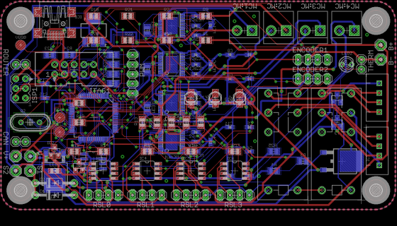
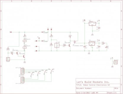
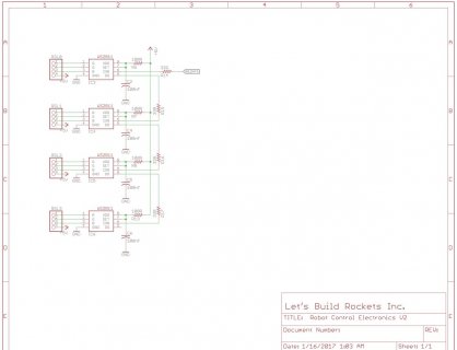
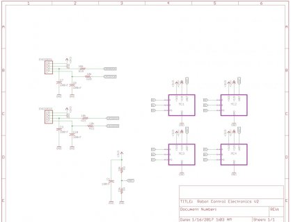
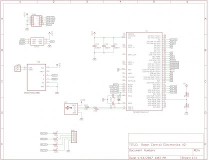
It is on a custom board. The schematic is attached. (Note: pin 8, vregin, has been jumped to the vusb)

We have been troubleshooting this for weeks with little success. I suspect that it is a hardware problem. Any help is appreciated.

Thanks,
Eric
 

Attachments

  • brd.png
    brd.png
    196.9 KB · Views: 220
  • sch - p1.jpg
    sch - p1.jpg
    84.2 KB · Views: 224
  • sch - p2.jpg
    sch - p2.jpg
    71.4 KB · Views: 208
  • sch - p3.jpg
    sch - p3.jpg
    74.3 KB · Views: 218
  • sch - p4.jpg
    sch - p4.jpg
    102.6 KB · Views: 245
Last edited:
Vbat is not connected(?)
And im not sure about vregin. Doesnt it need a connection, too ?
 
Last edited:
Hi Frank, Thanks for the reply. No, vbat is not connected. I thought/think that it is only for the RTC module. I hooked it up to 3v3 just now, but had no luck.
Vregin has actually been jumped to vusb (5v). In the datasheet or reference manual it says that vreg in is required for the usb module to work, but I still can't find anything about vbat.

-Eric
 
Ah that's quite interesting. I tried with both vbat connected and with the RTC init commented out with no luck. Same issue.

On that same page I see that "VREGOUT on the MK20 must be connected, even if you are supply 3.3V without using the MK20's built in voltage regulator.", but this thread doesn't make much sense to me. It seems that Scott had his vregin powered incorrectly and a fried MK20.
 
On that same page I see that "VREGOUT on the MK20 must be connected, even if you are supply 3.3V without using the MK20's built in voltage regulator.", but this thread doesn't make much sense to me.

It means you must connect 3.3V power to VREGOUT, even if not using the regulator.

I've edited the web page. Hopefully this longer version will make more sense?

VREGOUT on the MK20 must be connected, even if you are supply 3.3V without using the MK20's built in voltage regulator. The USB tranceiver power connects only to VREGOUT. Your board will fail to communicate over USB if VREGOUT does not have 3.3V power.

Connect 3.3V to VREGOUT out, and of course also VBAT. Hopefully those will bring your board to life?
 
Thanks Paul,

Ok, so I still haven't solved the problem.
I put a ZIF socket on some protoboard to debug.
I have 3v3 on pins 3,7,21,30,48. I have gnd on 4,31,47.
There is a jtag connector on pins 22,23,24,25,34.
USB is connected with the 5v line floating, and the D+ and D- connected to pins 5 and 6 through 33ohm resistors, and gnd, is connected to gnd.
16 Mhz Crystal tied to 32 and 33 with caps to ground.

Other than that, there is nothing connected. Same problem.

Am I missing something? The board only has like a dozen wires. I am thinking that it might be a code problem(?)
Anyways, if no one has any more ideas, I am going to switch to an ST chip instead.

Thanks for all the help!
-Eric
 
Last edited:
Status
Not open for further replies.
Back
Top