Bob Larkin
Well-known member
With the Audio Network Analyzer project, I found I needed to recalibrate the phase of the ADC-DAC path. This is with the PJRC SGTL-5000 Audio Board (and a teensy 3.6). I have explored this issue enough to understand the limitations this presents. The details are here in case any one else is doing phase-sensitive work.
NOTE - Nothing here should be of any interest to those doing audio processing for the ear. The ear will never notice a few tens of microseconds of shift!
First the results, and then the test setup. A signal is introduced through both line inputs of the ADC. This is directly sent to the corresponding DAC outputs of the audio board. The delay of this path, for the default 44117.65 sample rate is about 6350 microseconds. If the power is removed and reapplied, the delay through this path is often the same, but not always. A trial of 5 times showed 4 times for 6352 microseconds and once at 6358 microseconds. If the sketch is reloaded, the results are basically random, over a range of about 35 microseconds. Note that 35 microseconds is most of the 50 microsecond period for a 20 KHz signal, and for what I am doing is a big deal! BTW, both L & R channels track the shifts together.
That is the question of start-up, and for me just says that calibration is needed after things are powered down. This is OK. A second issue is that I use a combination of a 44.117 kHz and 100 kHz sample rates. I was worried that changing the sample rate would change the delay. As best that I can test it, it does not ever change the delay. My experiment changed the sample rate back and forth thousands of times with always consistent results for both rates.
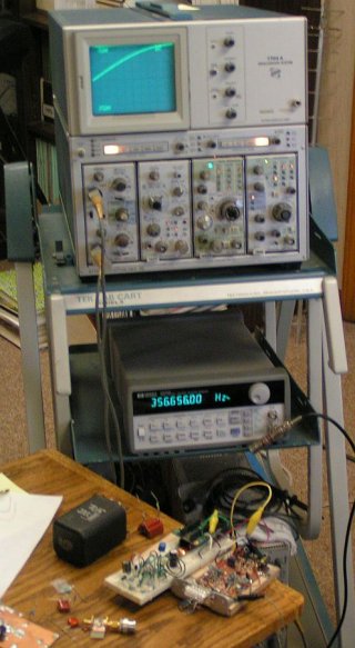
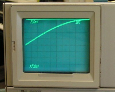
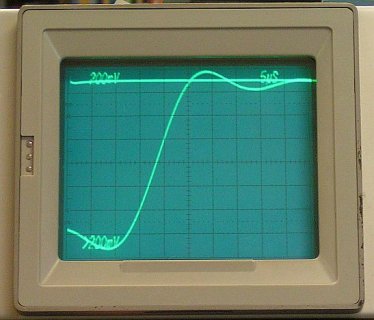
And the method of testing this. I hooked up a HP33120A waveform generator, set to produce a square wave. This instrument is crystal controlled and can be adjusted in 0.01 milli-Hz steps. This went into the ADC inputs, and also was used to trigger an analog 'scope. The output of the selected DAC went to a second channel of the 'scope. The frequency was adjusted until the half-voltage point of the rising DAC output exactly lined up with the rising edge of the square wave. By choosing the lowest frequency for which this will occur the period of the square wave is the delay through the path.
The sketch is pretty simple, but included anyway:
Code:
// passThruSync.ino   Bob Larkin 11 Feb 2017
// Check synchronism of ADC and DAC.  Explores two issues for a signal using a ADC-DAC pass through.
//  1 - Is the phase shift the same at multiple startups or reloads?
//  2 - After changing sample rates, and back, does the phase shift return to the same value?

#include <Audio.h>

// Variable sample rate from Frank B., see
// https://forum.pjrc.com/threads/38753-Discussion-about-a-simple-way-to-change-the-sample-rate
// As pointed out by Frank, the various routines, like waveform generator, are calibrated
// for 44.11765 and need to be corrected when other sample rates are used, e.g.,
//      waveform1.frequency(AUDIO_SAMPLE_RATE_EXACT/samplefreq*freq);
// Note Teensy 3.6:  F_CPU == 180000000, F_PLL == 180000000
// Returns exact sample frequency
double setI2SFreq(int freq)
  {
  typedef struct
    {
    uint8_t mult;
    uint16_t div;
    } __attribute__((__packed__)) tmclk;
  const int numfreqs = 5;
  // 44117 is nickname for 44117.64706
  const int samplefreqs[numfreqs] = { 44100, 44117, 48000, 96000, 100000 };
#if (F_PLL==16000000)
  const tmclk clkArr[numfreqs] = {{151, 214}, {12, 17}, {96, 125}, {192, 125}, {0, 0} };
#elif (F_PLL==72000000)
  const tmclk clkArr[numfreqs] = {{98, 625}, {8, 51}, {64, 375}, {128, 375}, {0, 0} };
#elif (F_PLL==96000000)
  const tmclk clkArr[numfreqs] = {{147, 1250}, {2, 17}, {16, 125}, {32, 125}, {0, 0} };
#elif (F_PLL==120000000)
  const tmclk clkArr[numfreqs] = {{205, 2179}, {8, 85}, {64, 625}, {128, 625}, {0, 0} };
#elif (F_PLL==144000000)
  const tmclk clkArr[numfreqs] = {{49, 625}, {4, 51}, {32, 375}, {64, 375}, {0, 0} };
#elif (F_PLL==168000000)
  const tmclk clkArr[numfreqs] = {{42, 625}, {8, 119}, {64, 875}, {128, 875}, {0, 0} };
#elif (F_PLL==180000000)
  const tmclk clkArr[numfreqs] = {{196, 3125}, {16, 255}, {128, 1875}, {219, 1604}, {32, 225} };
#elif (F_PLL==192000000)
  const tmclk clkArr[numfreqs] = {{147, 2500}, {1, 17}, {8, 125}, {16, 125}, {0, 0} };
#elif (F_PLL==216000000)
  const tmclk clkArr[numfreqs] = {{98, 1875}, {8, 153}, {64, 1125}, {128, 1125}, {0, 0} };
#elif (F_PLL==240000000)
  const tmclk clkArr[numfreqs] = {{147, 3125}, {4, 85}, {32, 625}, {64, 625}, {0, 0} };
#endif
  for (int f = 0; f < numfreqs; f++)
    {
    if ( freq == samplefreqs[f] )
      {
      while (I2S0_MCR & I2S_MCR_DUF)  ;
      I2S0_MDR = I2S_MDR_FRACT((clkArr[f].mult - 1)) | I2S_MDR_DIVIDE((clkArr[f].div - 1));
      return  (double)F_PLL * (double)clkArr[f].mult / (256.0 * (double)clkArr[f].div);
      }
    }
  }

// Audio Objects
AudioControlSGTL5000     audioShield;
AudioInputI2S            i2s1;
AudioOutputI2S           i2s2;
AudioConnection          Connect1(i2s1, 0, i2s2, 0);
AudioConnection          Connect2(i2s1, 1, i2s2, 1);

void setup()
  {
  AudioMemory(25);          // Way below this
  // The next line will not always give the same phase shift to a pass through
  // signal.  Restarting is usually, but not always, the same.  Reloading the
  // sketch give random shifts.  The range of shifts is around 35 microseconds.  For a
  // 20 kHz signal, this is a major part of a cycle.
  setI2SFreq(100000);       // or 44117, etc
  delay(100);
  AudioNoInterrupts();      // Use to synchronize all audio
     // Enable the SGTL5000 audio CODEC
     audioShield.enable();
     // Headphone volume, 0.0 to 0.8 is undistorted over full input ADC range
     audioShield.volume(0.0);
     audioShield.lineInLevel(2, 2);     // 2.2 V p-p max
     audioShield.lineOutLevel(19);      // 2.2 V p-p FS
  AudioInterrupts();
  }

void loop()
  {
  // Test multiple changes of sample rate for shifts in phase.  24 hour tests
  // of the following has ALWAYS given the same phase shift for both rates.
  //  Comment all out for single rate
  setI2SFreq(100000);
  delay(1000);
  setI2SFreq(44117);
  delay(1000);
  }


