I2S Input Question

Status
Not open for further replies.

gfvalvo

Well-known member
Hi All.

So, I'm embarking on a project where I will attempt to use this TI Chip:
http://www.ti.com/product/DIR9001/description
to decode an optical TOSLINK input and send the audio samples to the I2S Receiver of a Teensy 3.x for use by the Audio Library (namely FFT).

The Teensy's I2S Receiver will have to be in slave mode so that the DIR9001 can supply the bit clock and frame sync synchronous to the original sample rate of the TOSLINK input.

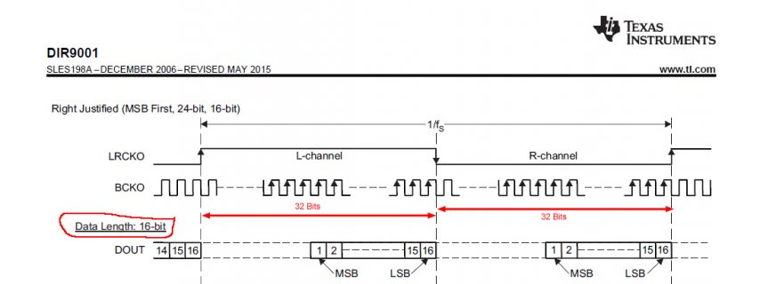
The only hitch I see is that the TI part has a fixed frame size of 2 words (Left and Right channels) and a fixed word size of 32 bits (i.e. 64 bits per frame). Knowing that the Teensy Audio Library operates on 16 bit samples, I've identified the settings in the TI chip to select 16 bit right-justified data in the 32 bit Left and Right channel locations:
TI.jpg
I've also gone through the MK20DX256 datasheet and identified the register settings necessary to support slave mode and 2 x 32 bit words (64 bit frame).

My only concern now is will the I2S Input, AudioConnection, and other facilities of the Audio Library properly pull the 16 bit samples from the lower 2 bytes of each 32 bit sample word. I'm a decent C coder, but don't know C++. So, I get pretty lost looking at the Library source code to find the answer to this question.

Sorry for the long-winded post. Hope that someone out there who's smarter than me can provide some guidance on this question.

Thanks.
 
Last edited:
Hi All.

So, I'm embarking on a project where I will attempt to use this TI Chip:
http://www.ti.com/product/DIR9001/description
to decode an optical TOSLINK input and send the audio samples to the I2S Receiver of a Teensy 3.x for use by the Audio Library (namely FFT).

The Teensy's I2S Receiver will have to be in slave mode so that the DIR9001 can supply the bit clock and frame sync synchronous to the original sample rate of the TOSLINK input.

The only hitch I see is that the TI part has a fixed frame size of 2 words (Left and Right channels) and a fixed word size of 32 bits (i.e. 64 bits per frame). Knowing that the Teensy Audio Library operates on 16 bit samples, I've identified the settings in the TI chip to select 16 bit right-justified data in the 32 bit Left and Right channel locations:
View attachment 9751
I've also gone through the MK20DX256 datasheet and identified the register settings necessary to support slave mode and 2 x 32 bit words (64 bit frame).

My only concern now is will the I2S Input, AudioConnection, and other facilities of the Audio Library properly pull the 16 bit samples from the lower 2 bytes of each 32 bit sample word. I'm a decent C coder, but don't know C++. So, I get pretty lost looking at the Library source code to find the answer to this question.

Sorry for the long-winded post. Hope that someone out there who's smarter than me can provide some guidance on this question.

Thanks.

Paul may correct me, but the standard Audio library expects frame- size (L+R words) to be 32 bit (16+16) and not 64 bit, as shown in the Figure.
Depending, what you wanted to use from the audio library, you may consider to do it without the library.
programming the I2S driver is not so hard.
There is not so much C++ in it, most routines are in C or C-style with a C++ wrapper.
If you like the whole audio library, you could take the I2S routines change them to 32 bit data mode (we, the forum, can help you) extract 16 bit (some sort of digital gain/attenuation) and use the rest of the Audio library.
Modifying the 32 bit frame to 64 bit frame, there are a couple of places you must modify, mainly
- bit frame register is I2S
- bit clock rate
- dma word length
- dma byte count
(loose terminology, but you can figure it out or we can help you, if you try to do that)
 
Hi, thanks for the reply. I would really like to make this input compatible with the rest of the library. I think I've already figured out (on paper anyway) the required register-level changes to the I2S Receiver subsystem. So, as you say, I should now take a look at the DMA.

Incidentally, the incoming Left and Right samples will be 16 bits each. They will just be embedded in the two lower bytes of their 32 bit words. The upper two bytes are padding that will be ignored So, I don't think any gain / scaling will be required. I just need to do byte manipulation to pull each 16 bit sample from its 32 bit container and then reformat them into the 2x16 stream that the library expects.

Thanks for the offer of assistance. I'll start going through the datasheets and source code again to see how far I get.
 
Paul may correct me, but the standard Audio library expects frame- size (L+R words) to be 32 bit (16+16) and not 64 bit, as shown in the Figure.

That's correct.

It may be possible to configure the I2S to a 64 bit frame, and have the DMA extract two 16 bit words. But so far nobody has made this work. It's on my low priority list of stuff to look into someday.

The words "low priority" and "someday" should be understood to mean the odds are slim I'll do much on it within 2017, if ever. But I be happy to merge a pull request if anyone can get this working.
 
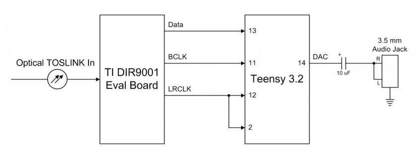
OK, I've succeeded in decoding an optical TOSLINK signal and feeding it into the Audio Library. The TOSLINK ---> I2S conversion is done by a TI DIR9001 (datasheet attached). Setup looks like this:
TOSLINK.jpg
The DIR9001 feeds 16 bit L and R samples embedded in 32 bit words (64 bit total frame size) to the Teensy's I2S RX input. See page 24 of DIR9001 datasheet. I created a new 'AudioInputI2S64Slave' class that extracts the two channels and feeds proper 'audio_block_t' samples to other Audio Library objects. All timing is derived from the sample rate of the incoming TOSLINK signal. So far, I've tested it with fs = 44.1 and fs = 48 KS/s.


I've also created a new 'AudioOutputAnalogI2S' class to synchronize the Teensy's DAC output to the incoming I2S signal. It does this by using the LRCLK input (essentially a clock at the sample rate) to trigger the DAC's DMA transfers. I use a separate input (Pin 2) for this trigger because I'm not sure if the LRCLK input (Pin 12) can simultaneously be a DMA trigger.

When I receive the Teensy Audio Shield that I ordered, I'll create a similar class to synch the Teensy's I2S Transmitter to the TOSLINK input. Then it can drive the CODEC on the Audio Shield to produce stereo output.

All code is below. Note, I'm not a C++ programmer (yet). So, I created these new classes by modifying the existing ones from the library. But, they are separate, independent classes. I did not attempt to make them sub-classes of the current ones with property inheritance, etc. Also, they're only coded for the Freescale MK20 family since all I have is a Teensy 3.2 board. I'll leave proper integration into the Audio Library and implementation for other processors as an exercise for an interested C++ coder. Right now, these implementations meet my needs.

.ino File:
Code:
#include "input_i2s64Slave.h"
#include "output_dac_SyncI2S.h"

#include <Audio.h>

AudioInputI2S64Slave     audioInput;
AudioMixer4              mixer1;
AudioOutputAnalogI2S     dac1;
AudioAnalyzeFFT1024      myFFT;

AudioConnection          patchCord1(audioInput, 0, mixer1, 0);
AudioConnection          patchCord2(audioInput, 1, mixer1, 1);
AudioConnection          patchCord3(mixer1, dac1);
AudioConnection          patchCord4(mixer1, myFFT);

void setup() {
  Serial.begin(115200);
  delay(1000);
  AudioMemory(20);
  myFFT.windowFunction(AudioWindowHanning1024);
  mixer1.gain(0, 0.5);
  mixer1.gain(1, 0.5);
}

void loop() {
  float n;
  int i;

  if (myFFT.available()) {
    // each time new FFT data is available
    // print it all to the Arduino Serial Monitor
    Serial.print("FFT: ");
    for (i = 0; i < 45; i++) {
      n = myFFT.read(i);
      if (n >= 0.01) {
        Serial.print(n);
        Serial.print(" ");
      } else {
        Serial.print("  -  "); // don't print "0.00"
      }
    }
    Serial.println();
  }
}

input_i2s64Slave.h:
Code:
#ifndef _input_i2s_64_Slave_h_
#define _input_i2s_64_Slave_h_

#include "Arduino.h"
#include "AudioStream.h"
#include "DMAChannel.h"

class AudioInputI2S64Slave : public AudioStream
{
  public:
    AudioInputI2S64Slave(void) : AudioStream(0, NULL) {
      begin();
    }
    virtual void update(void);
    void begin(void);
  protected:
    static bool update_responsibility;
    static DMAChannel dma;
    static void isr(void);
    static void i2sResetIsr(void);
  private:
    static audio_block_t *block_left;
    static audio_block_t *block_right;
    static uint16_t block_offset;
};
#endif

input_i2s64Slave.cpp:
Code:
#include "input_i2s64Slave.h"
#if defined(__MK20DX256__) || defined(__MK64FX512__) || defined(__MK66FX1M0__)

DMAMEM static uint32_t i2s_rx_buffer[2 * AUDIO_BLOCK_SAMPLES];
audio_block_t * AudioInputI2S64Slave::block_left = NULL;
audio_block_t * AudioInputI2S64Slave::block_right = NULL;
uint16_t AudioInputI2S64Slave::block_offset = 0;
bool AudioInputI2S64Slave::update_responsibility = false;
DMAChannel AudioInputI2S64Slave::dma(false);

void AudioInputI2S64Slave::begin(void)
{
  dma.begin(true); // Allocate the DMA channel first

  // Enable clock to I2S
  SIM_SCGC6 |= SIM_SCGC6_I2S;

  // Configure the RX, Slave mode, 64 bit frames
  I2S0_RMR = 0;
  I2S0_RCR1 = I2S_RCR1_RFW(2);
  I2S0_RCR2 = I2S_RCR2_SYNC(0) | I2S_TCR2_BCP;
  I2S0_RCR3 = I2S_RCR3_RCE;
  I2S0_RCR4 = I2S_RCR4_FRSZ(1) | I2S_RCR4_SYWD(31) | I2S_RCR4_MF;
  I2S0_RCR5 = I2S_RCR5_WNW(31) | I2S_RCR5_W0W(31) | I2S_RCR5_FBT(31);

  // Configure Pins
  CORE_PIN13_CONFIG = PORT_PCR_MUX(4); // pin 13, PTC5, I2S0_RXD0
  CORE_PIN12_CONFIG = PORT_PCR_MUX(4); // pin 12, PTC7, I2S0_RX_FS
  CORE_PIN11_CONFIG = PORT_PCR_MUX(4); // pin 11, PTC6, I2S0_RX_BCLK

  dma.TCD->SADDR = &I2S0_RDR0;
  dma.TCD->SOFF = 0;
  dma.TCD->ATTR = DMA_TCD_ATTR_SSIZE(2) | DMA_TCD_ATTR_DSIZE(2);
  dma.TCD->NBYTES_MLNO = 8;
  dma.TCD->SLAST = 0;
  dma.TCD->DADDR = i2s_rx_buffer;
  dma.TCD->DOFF = 4;
  dma.TCD->CITER_ELINKNO = sizeof(i2s_rx_buffer) / 8;
  dma.TCD->DLASTSGA = -sizeof(i2s_rx_buffer);
  dma.TCD->BITER_ELINKNO = sizeof(i2s_rx_buffer) / 8;
  dma.TCD->CSR = DMA_TCD_CSR_INTHALF | DMA_TCD_CSR_INTMAJOR;

  dma.triggerAtHardwareEvent(DMAMUX_SOURCE_I2S0_RX);
  update_responsibility = update_setup();
  dma.enable();
 
  I2S0_RCSR = I2S_RCSR_SR;   // Reset I2S RX 
  I2S0_RCSR = I2S_RCSR_BCE | I2S_RCSR_FRDE;  // Enable BCLK and DMA
  I2S0_RCSR |= I2S_RCSR_SEIE | I2S_RCSR_FEIE | I2S_RCSR_FWIE; // Enable interrupt on sync error, FIFO error, FIFO warning
  I2S0_RCSR |= I2S_RCSR_RE;  // Enable RX
  
  dma.attachInterrupt(isr);

  // Add ISR to reset I2S RX on sync error, FIFO error, FIFO warning
  // Have seen these occur when sample rate of input source changes (i.e. 44.1 <--> 48 KS/s)
  // I2S RX doesn't seem to recover on its own
  _VectorsRam[IRQ_I2S0_RX + 16] = i2sResetIsr;
    NVIC_ENABLE_IRQ(IRQ_I2S0_RX);
}

void AudioInputI2S64Slave::isr(void)
{
  uint32_t daddr, offset;
  const uint32_t *src, *end;
  int16_t *dest_left, *dest_right;
  audio_block_t *left, *right;

  //digitalWriteFast(3, HIGH);
  daddr = (uint32_t)(dma.TCD->DADDR);
  dma.clearInterrupt();

  if (daddr < (uint32_t)i2s_rx_buffer + sizeof(i2s_rx_buffer) / 2) {
    // DMA is receiving to the first half of the buffer
    // need to remove data from the second half
    src = (const uint32_t *)&i2s_rx_buffer[AUDIO_BLOCK_SAMPLES];
    end = (const uint32_t *)&i2s_rx_buffer[AUDIO_BLOCK_SAMPLES * 2];
    if (AudioInputI2S64Slave::update_responsibility) AudioStream::update_all();
  } else {
    // DMA is receiving to the second half of the buffer
    // need to remove data from the first half
    src = (const uint32_t *)&i2s_rx_buffer[0];
    end = (const uint32_t *)&i2s_rx_buffer[AUDIO_BLOCK_SAMPLES];
  }
  left = AudioInputI2S64Slave::block_left;
  right = AudioInputI2S64Slave::block_right;
  if (left != NULL && right != NULL) {
    offset = AudioInputI2S64Slave::block_offset;
    if (offset <= AUDIO_BLOCK_SAMPLES / 2) {
      dest_left = &(left->data[offset]);
      dest_right = &(right->data[offset]);
      AudioInputI2S64Slave::block_offset = offset + AUDIO_BLOCK_SAMPLES / 2;
      do {

        *dest_left++ = (int16_t)((*src++)&0xFFFF);
        *dest_right++ = (int16_t)((*src++)&0xFFFF);
      } while (src < end);
    }
  }
}

void AudioInputI2S64Slave::update(void)
{
  audio_block_t *new_left = NULL, *new_right = NULL, *out_left = NULL, *out_right = NULL;

  // allocate 2 new blocks, but if one fails, allocate neither
  new_left = allocate();
  if (new_left != NULL) {
    new_right = allocate();
    if (new_right == NULL) {
      release(new_left);
      new_left = NULL;
    }
  }
  __disable_irq();
  if (block_offset >= AUDIO_BLOCK_SAMPLES) {
    // the DMA filled 2 blocks, so grab them and get the
    // 2 new blocks to the DMA, as quickly as possible
    out_left = block_left;
    block_left = new_left;
    out_right = block_right;
    block_right = new_right;
    block_offset = 0;
    __enable_irq();
    // then transmit the DMA's former blocks
    transmit(out_left, 0);
    release(out_left);
    transmit(out_right, 1);
    release(out_right);
    //Serial.print(".");
  } else if (new_left != NULL) {
    // the DMA didn't fill blocks, but we allocated blocks
    if (block_left == NULL) {
      // the DMA doesn't have any blocks to fill, so
      // give it the ones we just allocated
      block_left = new_left;
      block_right = new_right;
      block_offset = 0;
      __enable_irq();
    } else {
      // the DMA already has blocks, doesn't need these
      __enable_irq();
      release(new_left);
      release(new_right);
    }
  } else {
    // The DMA didn't fill blocks, and we could not allocate
    // memory... the system is likely starving for memory!
    // Sadly, there's nothing we can do.
    __enable_irq();
  }
}

void AudioInputI2S64Slave::i2sResetIsr(void) {
  I2S0_RCSR = I2S_RCSR_SR;   // Reset I2S RX 
  I2S0_RCSR = I2S_RCSR_BCE | I2S_RCSR_FRDE;  // Enable BCLK and DMA
  I2S0_RCSR |= I2S_RCSR_SEIE | I2S_RCSR_FEIE | I2S_RCSR_FWIE; // Enable interrupt on sync error, FIFO error, FIFO warning
  I2S0_RCSR |= I2S_RCSR_RE;  // Enable RX
}


#else
#error only written for MK20DX25, MK64FX512, MK66FX1M0
#endif // defined(__MK20DX256__) || defined(__MK64FX512__) || defined(__MK66FX1M0__)

output_dac_SyncI2S.h:
Code:
#ifndef output_dac_h_
#define output_dac_h_

#include "Arduino.h"
#include "AudioStream.h"
#include "DMAChannel.h"

class AudioOutputAnalogI2S : public AudioStream
{
public:
	AudioOutputAnalogI2S(void) : AudioStream(1, inputQueueArray) { begin(); }
	virtual void update(void);
	void begin(void);
	void analogReference(int ref);
private:
	static audio_block_t *block_left_1st;
	static audio_block_t *block_left_2nd;
	static bool update_responsibility;
	audio_block_t *inputQueueArray[1];
	static DMAChannel dma;
	static void isr(void);
};
#endif

output_dac_SyncI2S.cpp:
Code:
#include "output_dac_SyncI2S.h"

#if defined(__MK20DX256__) || defined(__MK64FX512__) || defined(__MK66FX1M0__)

DMAMEM static uint16_t dac_buffer[AUDIO_BLOCK_SAMPLES*2];
audio_block_t * AudioOutputAnalogI2S::block_left_1st = NULL;
audio_block_t * AudioOutputAnalogI2S::block_left_2nd = NULL;
bool AudioOutputAnalogI2S::update_responsibility = false;
DMAChannel AudioOutputAnalogI2S::dma(false);

void AudioOutputAnalogI2S::begin(void)
{
	dma.begin(true); // Allocate the DMA channel first

	SIM_SCGC2 |= SIM_SCGC2_DAC0;
	DAC0_C0 = DAC_C0_DACEN;                   // 1.2V VDDA is DACREF_2
	// slowly ramp up to DC voltage, approx 1/4 second
	for (int16_t i=0; i<2048; i+=8) {
		*(int16_t *)&(DAC0_DAT0L) = i;
		delay(1);
	}

  // Configure to trigger DMA using LRCLK jumpered to Pin 2 
  SIM_SCGC5 |= SIM_SCGC5_PORTD;
  CORE_PIN2_CONFIG = PORT_PCR_MUX(1) | PORT_PCR_IRQC(2);
  SIM_SCGC6 |= SIM_SCGC6_DMAMUX;
  SIM_SCGC7 |= SIM_SCGC7_DMA;
 
	dma.TCD->SADDR = dac_buffer;
	dma.TCD->SOFF = 2;
	dma.TCD->ATTR = DMA_TCD_ATTR_SSIZE(1) | DMA_TCD_ATTR_DSIZE(1);
	dma.TCD->NBYTES_MLNO = 2;
	dma.TCD->SLAST = -sizeof(dac_buffer);
	dma.TCD->DADDR = &DAC0_DAT0L;
	dma.TCD->DOFF = 0;
	dma.TCD->CITER_ELINKNO = sizeof(dac_buffer) / 2;
	dma.TCD->DLASTSGA = 0;
	dma.TCD->BITER_ELINKNO = sizeof(dac_buffer) / 2;
	dma.TCD->CSR = DMA_TCD_CSR_INTHALF | DMA_TCD_CSR_INTMAJOR;
  dma.triggerAtHardwareEvent(DMAMUX_SOURCE_PORTD);
	update_responsibility = update_setup();
	dma.enable();
	dma.attachInterrupt(isr);
}

void AudioOutputAnalogI2S::analogReference(int ref)
{
	// TODO: this should ramp gradually to the new DC level
	if (ref == INTERNAL) {
		DAC0_C0 &= ~DAC_C0_DACRFS; // 1.2V
	} else {
		DAC0_C0 |= DAC_C0_DACRFS;  // 3.3V
	}
}


void AudioOutputAnalogI2S::update(void)
{
	audio_block_t *block;
	block = receiveReadOnly(0); // input 0
	if (block) {
		__disable_irq();
		if (block_left_1st == NULL) {
			block_left_1st = block;
			__enable_irq();
		} else if (block_left_2nd == NULL) {
			block_left_2nd = block;
			__enable_irq();
		} else {
			audio_block_t *tmp = block_left_1st;
			block_left_1st = block_left_2nd;
			block_left_2nd = block;
			__enable_irq();
			release(tmp);
		}
	}
}

void AudioOutputAnalogI2S::isr(void)
{
	const int16_t *src, *end;
	int16_t *dest;
	audio_block_t *block;
	uint32_t saddr;

	saddr = (uint32_t)(dma.TCD->SADDR);
	dma.clearInterrupt();
	if (saddr < (uint32_t)dac_buffer + sizeof(dac_buffer) / 2) {
		// DMA is transmitting the first half of the buffer
		// so we must fill the second half
		dest = (int16_t *)&dac_buffer[AUDIO_BLOCK_SAMPLES];
		end = (int16_t *)&dac_buffer[AUDIO_BLOCK_SAMPLES*2];
	} else {
		// DMA is transmitting the second half of the buffer
		// so we must fill the first half
		dest = (int16_t *)dac_buffer;
		end = (int16_t *)&dac_buffer[AUDIO_BLOCK_SAMPLES];
	}
	block = AudioOutputAnalogI2S::block_left_1st;
	if (block) {
		src = block->data;
		do {
			// TODO: this should probably dither
			*dest++ = ((*src++) + 32767) >> 4;
		} while (dest < end);
		AudioStream::release(block);
		AudioOutputAnalogI2S::block_left_1st = AudioOutputAnalogI2S::block_left_2nd;
		AudioOutputAnalogI2S::block_left_2nd = NULL;
	} else {
		do {
			*dest++ = 2047;
		} while (dest < end);
	}
	if (AudioOutputAnalogI2S::update_responsibility) AudioStream::update_all();
}

#else
#error only written for MK20DX25, MK64FX512, MK66FX1M0
#endif // defined(__MK20DX256__) || defined(__MK64FX512__) || defined(__MK66FX1M0__)
 

Attachments

  • dir9001.pdf
    990 KB · Views: 1,191
Last edited:
I know this thread is a bit old, but I am trying to determine the feasibility of reading a stereo 32-bit/sample 192K samples/sec stream via I2S. The data is in fact not audio so I don't need the audio library per se, but just want to get the bits in so I can do some processing on them and write them via USB. E.g. this is a data acquisition project where the data happens be be coming in the I2S protocol at what works out to 12.288Mbps. Is the teensy capable of reading at this rate?
 
I know this thread is a bit old, but I am trying to determine the feasibility of reading a stereo 32-bit/sample 192K samples/sec stream via I2S. The data is in fact not audio so I don't need the audio library per se, but just want to get the bits in so I can do some processing on them and write them via USB. E.g. this is a data acquisition project where the data happens be be coming in the I2S protocol at what works out to 12.288Mbps. Is the teensy capable of reading at this rate?
Yes, Teensy can handle this, but as the audio library is fixed 16 bit and 44.1 kHz sampling, you may need to write your own software building on the few (many?) examples posted/discussed here on 32 bit I2S data acquisitions. Depending on processing, you may wanted to choose T3.6 which can perform hardware floating point processing
 
This would be externally clocked with a bit clock of 12.288MHz. I can probably generate a word clock every 32 bits (to make this look like two (e.g. R/L) 16 bit samples per word) instead of the 64 bit word clock I currently have. Since I will do no audio processing with the library I don't care if the library is built for 16 or 32 bit samples so long as it can get all the bits into memory where I can get to them.

The goal is to write this data to a USB drive without ever missing an incoming sample on a continuous basis (it must runs for hours).

My real concern is if the USB data can be written while still reliably handling the interrupts from the incoming I2S stream. I have implemented this on a Raspberry Pi and it *almost* works reliably. It suffers from occasional overruns when the linux o/s gets busy writing the USB disk and takes too long to service the I2S stream. After many attempts to tune the o/s, use multiple buffers, etc., I have about concluded it cannot be made to work reliably with that o/s. Hence I think I have to be closer to the hardware (like Teensy).

Thanks for any thoughts...

AFAIK, but Paul may correct me, USB has it own timing rules that may not easily be compatible with I2S (better DMA) interrupts.
But if you modify the USB routines to be 192 kHz friendly and adjust your DMA buffer size to be a multiple of this USB buffer size, you should have a nice system.

However, what I do not understand is, if your data is 2-chan 32 bit data, why do you want to simulate (four) 16 bit channels and make the DMA more complicated?
 
Sadly, the USB side isn't there yet. USBHost_t36 will someday support USB mass storage, but today it does not.

So I understand that to mean I cannot write a USB drive from the Teensy. But the Teensy can look like a USB device to a host, is that correct? I may have an Rpi host in the design anyway for other purposes I might use that to read from the Teensy and write the USB storage. From this page (https://www.pjrc.com/teensy/rawhid.html) it says the Raw HID mechanism is limited 1000 64-byte transfers per second (512Kbps... a long way from the 12.288Mbps I need). I wonder what is the nature of that limitation? The serial USB client (https://www.pjrc.com/teensy/usb_serial.html) says it runs at "full USB speed" (baud rate is ignored). For USB 2.0 that is (in theory) 480Mbps, way more than I need, but is a sustained rate of 12+Mbps practical? This is slow by USB standards.
 
However, what I do not understand is, if your data is 2-chan 32 bit data, why do you want to simulate (four) 16 bit channels and make the DMA more complicated?

In reality my data is 1 channel, 64 bits. If there is existing code that will read that from I2S as 4 channels of 16 bits each I am OK with that. I would prefer to not have to rebuild any library code (esp. DMA stuff) so I was just thinking to use the existing 16 bit libraries and I can change my word clock to transition every 16 bits instead of every 64 bits. For me it is easier to change the hardware than the Teensy libraries.
 
The names for USB speeds (as defined in the USB specs published by the USB-IF) are:

low = 1.5
full = 12
high = 480
super = 5000 or 10000

The USB device port on all Teensy 3.x is full speed, 12 Mbit/sec.

Teensy 3.6 has a 2nd high speed 480 Mbit/sec port, but it currently only supports host mode.
 
Yeah, I realized after posting that "full speed" is not 480Mpbs. So it seems there is not a way to do this (yet) on the Teensy. Sigh. Back to hacking Raspbian and the joys of linux device drivers.
 
Honestly, even if we had the software support, this might still be beyond Teensy 3.6 capability. Maybe?

Future Teensy with Cortex-M7 (and eventually software support for this stuff) will probably be up to this task....
 
Status
Not open for further replies.
Back
Top