Pwm on teensy 3.1

Status
Not open for further replies.

Borja

Active member
Good evening,

I bought a teensy two years ago but so far I've used not so long. A colleague and I were working with microchip pic16 to generate a quasi-sinusoidal wave and control 3-phase motors writing the code in asm but it's so difficult to translate these codes into C without losing any information.

We used a set of pulses with 16-20 kHz frequency switching the states of the pins on/off using the timers.

1. Load the prescaler of the timer in a register and start to count
2. Wait until the overflow of the timer and activation of the "overflow" flag
3. Change the state of a pin/several pins on/off or off/on
4. Load another prescaler and repeat the above operations until the loop is finished
5. Repeat repeat and repeat the loops

During the cycle the on and off time changes for this reason I think I can't use a simple analogwrite.

I read the datasheet but I don't know how to access to the timers and change the prescaler, read the "overflow" flag and change the correct register to switch the state of a pin.

The microchip pics worked at 16/64 MHz (250/62,5 ns per instruction), how long is an instruction on this teensy?

May anyone help me with this?

Thanks

IMG_1206.PNG
 
Hi,

when you use the Arduino IDE with Teensyduino to program your Teensy in C++, you can use some very powerful high-level commands to control the PWM. No need to look into timers and overflow flags, the libraries provided with Teensyduino will take care of this. Hava a look at this to get started: https://www.pjrc.com/teensy/td_pulse.html
You'll want to look up how to use
analogWrite();
analogWriteFrequency();
analogWriteResolution();

Hope this will get you started.
Ben

PS: For timing look into elapsedMillis (an automagically increasing variable) and intervalTimer(calls a user-defined ISR in regular time intervals).
 
Good evening,

I've just used those functions with constants pwm for example to blink a led. I choose a frequency and a duty and the teensy does the rest.

However my problem is to generate a sinusoidal wave with variable pulses with a six mosfet full bridge.

For example if the motor must work at 100 Hz the whole wave lasts 10ms. During the first 90 degrees of this wave (0-2.5 ms) we turn on and off six times three of six mosfets.

The pulses lasts around 70 microseconds on and 350 microseconds off, after that again on around 140 us and 280 off ....

The on and off time is changing and this time is very short and the transition between theses pulses must be less than 500ns. We wrote the code in asm because it was impossible with low cost microchip pics in C.

My question is it possible to do this with teensy in C or I have to use registers and flags?
 
Hi,
I'm on vacation right now, so I'm sorry I can't try anything myself at the moment. You could try to set up an ISR that updates the duty cycle of all the PWMs and call it regularly. Toggle a pin at the beginning and end of the ISR, this way you can measure ISR execution time with a scope. Maybe the ISR is fast enough so you can call it at the desired speed.
Ben
 
Hi,

no problem I can await your response when you are back home.

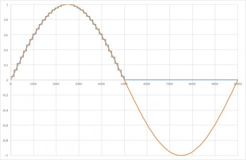
I tried to draw in Excel a picture with this quasi-senoidal wave only at 100Hz and 18 steps (nearly 139 us each step). To control a motor I have to use a full bridge with 6 mosfets and each mosfet has the same times but a fixed time delayed.


The first 90 degrees (at this frequency 0-2.5ms) for the mosfet 1 are:

Step 1: 0-139us Duty=4.4% Ton=6us Toff=133us
Step 2: 139-278us Duty=13% Ton=18us Toff=121us
Step 3: 278-417us Duty=21.6% Ton=30us Toff=109us
Step 4: 417-556us Duty=30% Ton=42us Toff=97us
Step 5: 556-694us Duty=38.2% Ton=53us Toff=86us
Step 6: 694-833us Duty=46.1% Ton=64us Toff=75us
Step 7: 833-972us Duty=53.7% Ton=75us Toff=64us
Step 8: 972us-1111us Duty=60.8% Ton=85us Toff=54us
Step 9: 1111-1250us Duty=67.5% Ton=94us Toff=45us
Step 10: 1250-1389us Duty=73.7% Ton=102us Toff=37us
Step 11: 1389-1528us Duty=79.3% Ton=110us Toff=29us
Step 12: 1528-1667us Duty=84.3% Ton=117us Toff=22us
Step 13: 1667-1806us Duty=88.6% Ton=123us Toff=16us
Step 14: 1806-1944us Duty=92.3% Ton=128us Toff=11us
Step 15: 1944-2083us Duty=95.3% Ton=132us Toff=7us
Step 16: 2083-2222us Duty=97.5% Ton=136us Toff=3us
Step 17: 2222-2361us Duty=99.1% Ton=138 us Toff=1us
Step 18: 2361-2500us Duty=99.8% Ton=139us Toff=0us

Duty=Ton/(Ton+Toff)
Steps from 19 to 36 have the same times but backwards and from 5,000us to 10,000us this mosfet must be off and later start again the step 1.

For this reason I need 6 independent timers for switching on/off 6 pins of the microcontroller and generate the set of pulses for each mosfet at the same time. I hope you know what I'm trying to explain.

With the Microchip Pics we did only 3 steps to control the motor but I think Teensy can do it with more levels :)


figure18.png
Mosfet 1.jpg
 
Are all six output uniquely adjustable or common value at a given time? Are they either cycling and running or just Off?
 
Hi,

I don't know if I understood your question. The values of my last post are common for all six mosfets but not at the same time. At every step three mosfets are completely off and the other three are switching on and off according with the value of the duty. For example at a step the mosfets 2,3,5 are off mosfet 1,4,6 are switching on and off with duties 80%, 30% and 50%.

Next task is to adjust the frequency/speed with a potentiometer/accelerator and read the output with a adc channel of the teensy every 50ms or so.

Sorry but I don't know if I answered your question, may you explain what you meant?
 
Before I start answering the many questions, I'd like to mention Teensy has a feature called DMA. It's complex to use, but it'll be well worth the trouble to learn.

Now, about some of those specific questions....


During the cycle the on and off time changes for this reason I think I can't use a simple analogwrite.

You can use analogWrite, but you'll need to do it within every PWM cycle. The PWM is double buffered, so no matter where in the cycle you write, the current cycle completes with the prior setting and the next cycle begins with the setting you wrote during the prior cycle.

I read the datasheet but I don't know how to access to the timers and change the prescaler, read the "overflow" flag and change the correct register to switch the state of a pin.

I don't understand why you're asking to "the correct register to switch the state of a pin". You don't directly manipulate the pin. The timer control the pin. You write a number to the timer channel register. The timer drives the pin high at the beginning of the cycle, the moment it rolls back to zero. Then the pin is driven low later in the cycle, when the timer increments to whatever number you put into the register. When using PWM you don't ever control the pin directly.

In the MK20DX256 reference manual, these timer registers are documented in chapter 36, starting on page 769.

The prescaler setting and overflow flag are in the FTM0_SC register, section 36.3.3 starting on page 780. The register that controls how far the timer counts is FTM0_MOD on page 782.

The timer has 8 channels, so it can create 8 PWM signals related to the same timer. Each channel is controlled by a config register and a value register, which are documented on pages 783 to 786.

The microchip pics worked at 16/64 MHz (250/62,5 ns per instruction), how long is an instruction on this teensy?

By default Teensy 3.2 runs at 96 MHz. Most instructions execute in a single cycle, or 10.42 ns. However, sometimes 2 or more cycles are needed, for a variety of reasons.

It's probably also worth mentioning the timers run from a slower clock, usually 48 or 60 MHz. The achievable PWM resolution is related to this F_BUS clock speed.


The pulses lasts around 70 microseconds on and 350 microseconds off, after that again on around 140 us and 280 off ....
....
The on and off time is changing and this time is very short and the transition between theses pulses must be less than 500ns. We wrote the code in asm because it was impossible with low cost microchip pics in C.

My question is it possible to do this with teensy in C or I have to use registers and flags?

It's definitely possible to do with Teensy 3.x using only C / C++ programming.

I do not recommend trying to write a tight loop to poll the hardware, as you'd do on a PIC. Teensy is far more powerful, and you can use that power to do things very easily in ways that are easier to maintain and won't break when you make minor changes to the code.

The simpler way would involve using an interrupt from the TOF (timer overflow) bit in FTM0_SC. To do this, you'd attachInterruptVector to put your function into the interrupt table, then set TOIE and use NVIC_ENABLE_IRQ to turn on the interrupt. Then your function will run every time the timer overflows. Just write the next 6 numbers in the 6 PWM channel value registers.

The more advanced way would be to configure 6 DMA channels (or perhaps just 1 with tricky minor loop settings) to copy the numbers from a big buffer in memory automatically do the channel value registers, triggered every time the overflow bit occurs. Sadly, on Teensy 3.1 & 3.2, there isn't a TOF DMA trigger. Teensy 3.6 has this, so the best path might be to go right to 3.6.

To to this on Teensy 3.2, you'd have to dedicate one of the 8 timer channels to a minimum width PWM pulse. Then that channel could trigger the DMA, which would write to 6 of the other 7 channels.

You can set the DMA up to repeat automatically, so it will just keep copying the memory buffer to the PWM channels automatically. Then your program doesn't need to do anything at all. You can just sit back and let the DMA do all the fast data movement, and of course rewrite the numbers in buffer if you want to change the waveform.


Steps from 19 to 36 have the same times but backwards and from 5,000us to 10,000us this mosfet must be off and later start again the step 1.

Freescale actually packed the timer's PWM with tons of awesome features, for just the sort of thing you're trying to do. Pairs of PWM can be controlled together with programmable dead time. But it's a lot of complex settings.

For this reason I need 6 independent timers for switching on/off 6 pins of the microcontroller and generate the set of pulses for each mosfet at the same time. I hope you know what I'm trying to explain.

Yes, I understand. It looks like pretty standard 3 phase power synthesis.

You don't use 6 independent timers. You use 1 timer with 6 independent channels that all work from the same time base. The FTM timer is designed to do exactly what you want.

With the Microchip Pics we did only 3 steps to control the motor but I think Teensy can do it with more levels :)

I believe you'll be amazed what Teensy can do for you, if you leverage the DMA channels. It's probably capable of much faster than your mosfet driver circuitry can handle.

I don't have time to get into the details right now, but I'll mention the audio library has a PWM output that outputs a 88.2 kHz PWM signal and every cycle is controlled by 2 copies of each audio sample. Maybe take a look at that code....
 
Hi,

I don't know if I understood your question. The values of my last post are common for all six mosfets but not at the same time. At every step three mosfets are completely off and the other three are switching on and off according with the value of the duty. For example at a step the mosfets 2,3,5 are off mosfet 1,4,6 are switching on and off with duties 80%, 30% and 50%.

Next task is to adjust the frequency/speed with a potentiometer/accelerator and read the output with a adc channel of the teensy every 50ms or so.

Sorry but I don't know if I answered your question, may you explain what you meant?

Indeed that is the answer to my question.
 
Hi Paul,

I read your post and I still have a couples of doubts:


I didn't know that the Analogwrite is double buffered and I guess that is an very useful if there is only a mosfet but with 6 mosfets switching on and off simultaneously, wouldn't be a chaos?


My problem is that I'm still thinking as I am using a PIC. These PICs have several 8-bit registers such as PORTx or TRISx and I need to change the state of one-to-eight I move a 8-bit number to a working register and after from this register to the PORTx/TRISx and these registers change the status of the pins. If I move the number 11110000 to the register I switch on 4 pins and off the others.

If you want to change the state if a pin at a point of the program how do you change the state?


Does this timer have only an overflow flag or a flag for each channel?

Tomorrow I check your two proposals and try to do something but where can I read more about DMA?

Thanks!
 
I didn't know that the Analogwrite is double buffered and I guess that is an very useful if there is only a mosfet but with 6 mosfets switching on and off simultaneously, wouldn't be a chaos?

No, not chaos. All 6 are from the same timer, so all PWM waveforms are always perfectly in sync. You can write 6 new values anywhere within the cycle, and then all 6 will create their new setting perfectly in sync on the next cycle.


My problem is that I'm still thinking as I am using a PIC.

Yes, indeed. Those old 8 bit PIC chips were pretty primitive even in the mid-1990s.

The 32 bit ARM chips on Teensy are an incredible difference from those old PIC chips!


If you want to change the state if a pin at a point of the program how do you change the state?

If the pin is in GPIO mode (not controlled by a timer), use digitalWriteFast(pin, HIGH).

Does this timer have only an overflow flag or a flag for each channel?

There's only 1 overflow flag in the timer. Each channel has its own "match" flag, the moment the timer happens to increment to a number that's the same as the channel's value.

But there's only one number that's rapidly incrementing and rolls back over to zero, so there's only 1 overflow flag.


Well, except Teensy 3.2 has 3 of these timers and Teensy 3.5 & 3.6 have 4 of them. But for your application, use only the FTM0 timer.


Tomorrow I check your two proposals and try to do something but where can I read more about DMA?

Perhaps experiment without DMA first to become more familiar with how things work. DMA is really tough to troubleshoot, and pretty much impossible to apply until you have a solid understanding of the timer which the DMA will be accessing.
 
Hi,

Today I couldn't do anything but I have time this weekend and I try to compile a easy code with a variable pwm and I'm pretty sure that I'll find more problems and doubts.

Just one more thing for today, when I use the function analog write the pwm is left aligned isn't it? May be centered or right aligned? Is it possible to modify the alignment with analog write?

When I activated a pin with digital write I measured 3.25V so I deduced all the pins are 3.3V and have the state on with a voltage around 3.25V. Is the voltage for on state with analog write around these 3.25 V too?

Thanks!
 
Hi Paul,

I was reading several chapters of the data sheet and I found a register that can be useful for me:

49.2.1 Port Data Output Register (GPIOx_PDOR) Page 1335

This register configures the logic levels that are driven on each general-purpose output pins.

if I choose 6 digital pins of the teensy and find their bits of these registers, can I change the state of these pins directly only writing 0 or 1? For example pins 14-29?

Sin título.jpg

According to the 3.8.2.1 Instantiation Information the Timer0 has 8 channels so I can use this timer for my project but I can't understand after reading the datasheet what I have to do:(

1. First of all clear the timer0 on FTM0_SC bit 7 write 0
2. Disable the Timer interrupts of the timer0 on FTM0_SC bit 6 write 0
3. Setup the timer counting in up-mode on FTM0_SC bit 5 write 0
4.Select the clock source as clock system on FTM0_SC bits 4:3 write 01
5. Load the prescaler on FTM0_SC bits 2:0 write 000 (divide by 1)
Several of these setups are only available when MODE[WPDIS] = 1, what's that?
The current value of the counter is on FTM0_CNT but if there are 8 channels

6. Write on FTM0_MOD bits 15:0 the value of the counter which sets the bit Timer overflow flag. For example count 1 us (value of the counter 120=0x0078)
7. Write on FTM0_CNTIN bits 15:0 the initial value of the counter 0x0000?
8. Check the bit TOF, if it's 0 wait, else GPIOx_PDOR=0 or GPIOx_PDOR=1 depends on the pin.
9. Load a new value on FTM0_MOD, clear FTM0_CNTIN or automatically is cleared? and goto 8

My Teensy is overclocked at 120MHz, hence every 8.33ns the counter will be modified, won't it? When the TOF is set, does the counter start again at 0 or what I have to do?

May you have a look to this and help me?

Thank you so much!!
 
Hi everybody,

I was writing this weekend a very easy code to clear all the pins of PORTB and after 5us set all the pins of portB and after 5us again clear the portB.

Teensy sets the pins after 5us but after other 5us doesn't clear the port.

Futhermore I read 3.3V on several pins of the Teensy but not on the pins of the label PTBx according to this schema https://www.pjrc.com/teensy/schematic.html

May anyone help me to debug this code?

Thanks

#include <stdint.h>
#include "mk20dx128.h"
#include "core_pins.h"

void setup() {
// put your setup code here, to run once:

FTM1_MODE=0x04; // Disable WPDIS
FTM1_MODE=0x05; // FTM registers active


GPIOB_PDDR=0xFF; //PortB output
GPIOB_PDOR=0x00;
FTM1_SC=0x08; //Setup Timer1

}

void loop() {
// put your main code here, to run repeatedly:

PORTB=0x00;
FTM1_MOD=0x258; // 0x258=600=5us
FTM1_CNTIN=0x00; Counter 0

while((FTM1_SC & (1<<7))==0) While TOF is 0 repeat and wait
{

};

PORTB=0xFF;
FTM1_SC=0x0008;
FTM1_MOD=0x258;
FTM1_CNT=0x00;
FTM1_CNTIN=0x00; // Counter again 0

while((FTM1_SC & (1<<7))==0) While TOF is 0 repeat and wait
{

};
}
 
Status
Not open for further replies.
Back
Top