Reset audio board codec SGTL5000 in realtime processing

Status
Not open for further replies.

DD4WH

Well-known member
I use the two stereo channels of the Teensy audio board for I & Q channel for a Software Defined Radio. In order for the radio to work properly, I & Q have to be exactly 90 degrees out of phase, which they are, because they are produced like this in a hardware radio frontend.

However, sometimes -especially after having uploaded new software to the Teensy- the Teensy audio board codec seems to have a hickup and start with the wrong foot. This leads to I & Q inputs having the same phase, because obviously (my interpretation, can not measure that) the codec seems to use the wrong order for the input samples (something like I,I,Q,I,Q,I,Q). But: They have to be like I,Q,I,Q,I,Q,I,Q etc.

Curiously, we have the same issue with a software defined radio working with a different processor (STM32F4) and a different codec (WM8731) in the mcHF Transceiver. In this radio, a software initiated reset of the codec works to completely eliminate this problem, if it occurs.

So my question is:

Is it possible to reset the audio board codec SGTL5000 during runtime without having to cut power from the Teensy and audio board for a restart?
If it is possible, how could I do that?

All the best,

Frank DD4WH
 
Hm that looks more like a softwareproblem. Otherwise it would mean the SGTL swaps left&right channels - did i understand you correctly?
 
hi Frank,

could be, but the probability is low. If it was a software problem, it would be strange, that the same error occurs on two different hardware platforms with two different firmwares.

The SGTL would not swap the channels, but the acquisition of the samples would not be synchronized in the correct way, that´s my interpretation: so that the I & Q samples do not have the right time position to each other --> phase difference is then not 90 degrees, but 0 degrees --> leads to no mirror rejection in the radio signals.

One observation is, that the problem only occurs from the very beginning at startup, NEVER during runtime. And it´s only curable by a new boot.

So, do you know of a way to reset the codec during runtime? there is the "enable"-command, but is there also a "disable"?

All the best,

Frank
 
Frank, the only mention of a reset in the datasheet is this:

RESET
The SGTL5000 has an internal reset that is deasserted 8 SYS_MCLKs after all power rails have been brought up. After this time communication can start. See Dynamic Electrical Characteristics.
 
Question: Does it occur after power-on, too ? I guess, the problem probably occurs when resetting/re-programming the Teensy - because the SGTL stays running without reset.
Maybe you have to add a FET or other switch that disconnectes the power from the SGTL. Maybe it is possible to switch it with the Teensy-Reset-Line ?
 
The SGTL on the audio board stays ON while programming!!???? Is that true? That would explain everything . . .

It´s exactly like you said: the problem occurs VERY OFTEN directly after programming, SOMETIMES after power-on of the whole system (Teensy plus audioboard) and NEVER during operation.

Thanks a lot, Frank! That is a very probable explanation and I will make up my mind how to switch off the codec during reprogramming!

All the best,

Frank
 
Maybe the simplest solution is a pushbutton that opens - the +5V (=red) connection in the usb-cable :)
I have such a hacked cable with added pinheaders. It is possible to connect a jumper, amperemeter or switch.
 
Last edited:
Frank: This is an intriguing problem. How could the 2 ADC channels get so far out of sync as to cause the I,Q phase relationship to be incorrect? The delay would have to be many times longer than the sample rate. If this could happen, then those people using the SGTL for normal stereo audio purposes, would hear this as a mis-phasing of the stereo signal, which gives a comb-filter effect, which is quite noticeable. I have not heard reports of this, nor experienced it myself.
If, on the other hand, the SGTL gets switched to a mono mode, and is sending the same information on both channels, then your I/Q problem would show up and there would be no image rejection at all. In the SGTL CHIP_ANA_POWER register bit 6 is the ADC Mono select, which puts the ADC in mono mode. Maybe something is going wrong there sometimes at reset, and could be corrected by re-writing this register later on, in your code. Alternately, this register can turn on/off all of the individual parts of the SGTL5000 individually, so I am wondering if you could achieve the equivalent of a hard -reset by toggling all of the SGTL sections on/off in your code. I am not sure if this register is exposed by the audio library, but I have modified the .h file in my setup to make all SGTL registers public, as well as changing the register read/write routines to public so I could alter registers for some of the things that I do that are not in the audio lib.
I've built my own SDR RF front end and tried out your Teensy SDR program. What a superb piece of programming that is! Your choice of the PJRC small TFT screen makes lots of sense given its low price. But, I have some larger LCD touch screens based upon the really powerful FTDI FT800 graphics engine that I thought would make a great SDR display. In particular, I had a basic waterfall routine I wrote for it which works OK in its own sketch. However, trying to get that and the other necessary display elements working properly when patched into your program has eluded me so far. The FTDI FT800 library is meant for Arduino, and the SPI transport routines seem to be problematic when used with the Teensy and your SDR program (likely related to interrupts).
I may not get this combination working, but I have spent some time poring over the 4000+ lines of code you wrote, and am very impressed.
Regards
 
@bmillier:
What's the max. SPI- clockspeed of the FT800 ?
Does it support a 256 color (8-bit/pixel ) mode ?
Where did you buy yours ?
 
@Frank
The max SPI clock rate is 30 MHz. (they say to use <11 MHz for the initialization code routine, but the Teensy's 12 MHz works fine.
No- the highest color depth is RGB565 (although there is a pallete mode which allows you to define a 256 color palette)
There are a few sources of TFT modules. FTDI themselves sell some modules:
http://www.ftdichip.com/Products/Modules/VM800B.html
Mikroelektronika sell a module thats a bit less expensive:
https://shop.mikroe.com/add-on-boards/display/connect-eve

I have used both of these. There are others too: Riverdi started using them later on, after I had already started using the ones above- I haven't tried theirs.
The FT800 is completely different from the normal TFT controllers in use in small displays. You feed it a group of high level drawing commands to a display list, and then tell the device to execute that display list. It does very fast rendering, but this concept is not perfectly suited to a display for your SDR for example. In your code you would only update the parts of the display that are changing- the spectrum display or button changes, for example. For the FT800, you basically have to regenerate a whole new display list for each screen appearance change.( at least at my level of understanding of the code) But, this can be accomplished pretty quickly via SPI, given the high level of the graphics commands. However, for a waterfall display, for example, you only have to send it the pixels for 1 horizontal line/update. The older lines remain in the FT800 RAM and you can just shift a pointer to give you that waterfall effect.
Unlike the ILI9341, where a lot of your display code is dedicated to "erasing" text when updates occur, for FT800 you just send whatever text you want displayed, and you don't have to erase the previous text.
That being said, I am finding that the FT800 display will "crash" fairly quickly when I try to display anything using my patched version of your SDR code. When this happens, on my scope I see a constant stream of SPI data going to/from the FT800 even though the display is blank or dead. It looks like the Teensy is constantly checking for an acknowledgment of some sort from the FT800- and not getting it.
I'm sure there is a solution to this, but I haven't found it yet.
 
Thank you for all the info! I think i will buy such a Display.
By the way, we are two "Frank" - DD4WH lives some 100kM from here :)
 
Yes- I thought I was answering DD4WH, the other Frank who wrote the SDR code. I guess I'm getting like my wife- an admitted "half-looker".
I think that Glyn in Germany also makes displays with the FT800 controller.
It would be nice if some Teensy forum members started to develop some expertise with these displays- they are quite powerful.
 
bmillier,

thanks for your message! Yes, I agree, a single sample would not make a 90 degree difference. The "mono register"-explanation seems reasonable!

Very nice to hear that you got the Teensy Convolution SDR to work with your hardware! At the moment I am trying hard to implement an auto-notch/noise reduction to work, but that´s extremely hard/maybe too hard for me to implement.

I would be very interested in how I can change the CHIP_ANA_POWER register, especially the MONO option ;-). I am not at all familiar with this register switching, so if you have a hint on how to do that, it would be very much appreciated!

Have fun with the Teensy,

Frank DD4WH
 
Hi Frank: I don't want you to waste time on this if it turns out to be a dead end. I have already patched my control_sgtl5000.h file to move the register "read" and "write" routine declarations from the protected section to the public section. So, I can read/write the SGTL registers from my main sketch.
I see in the control_sgtl.cpp file, in the SGTL5000.enable routine, Paul sets up this register as follows: (line 521)
write(CHIP_ANA_POWER, 0x4060); // VDDD is externally driven with 1.8V
So, I think I can just write a zero to this register to remove power to everything, wait a bit, and then probably just call the SGTL5000.enable routine again. I think this should perform a hard-reset on the chip.
As I mentioned, I have been playing with the FT800 display on my Teensy SDR circuit, so it is not really functional as it would be if it were hooked to the PJRC 2.8" display.But, when I get a chance, I'll give this a try, and see if works enough to bring the SGTL5000 back to life again and sending out some audio. I haven't seen the I/Q problem myself, so I couldn't tell you if it cured that, however.
 
@Frank: As mentioned in my post above, I added a function to the SGTL5000 class called disable, which turns off all the power to the SGTL5000.(actually there already was a function called disable which did nothing - i.e. a null function). The function works BUT if you call it after the audio has started playing, subsequently calling the enable routine doesn't restore the audio because the Teensy has continued to send data to the SGTL5000 while it was shut down. The sketch continues to run (i.e. I can still see serial debug data on the PC monitor) and the Teensy LED which is on one of the I2S lines is still lit as it is normally during audio. But, there is no audio. One would have to disable the background audio process before doing this "disable" function, I think, to overcome this. So that makes the hard-reset of the SGTL5000 somewhat harder to accomplish.
I also added another function to the SGTL5000 class: setADCStereo. All this does is read the current value of CHIP_ANA_POWER) register, and then set its ADC_MONO bit to a 1 (stereo mode and power up default). You can call this while the audio is playing without disruption.
here are the lines of code for both of these functions:
in sgtl5000.h
AudioControlSGTL5000(void) : i2c_addr(0x0A) { }
void setAddress(uint8_t level);
bool enable(void);
bool disable(void); // originally { return false; }
bool setADCStereo(void);

(the last two lines are what I added)

in sgtl5000.cpp:

bool AudioControlSGTL5000::disable(void)
{
Wire.begin(); // need this and the following line if this routine is called prior to the enable command
delay(5);
write(CHIP_ANA_POWER, 0x0); //shut down all power to different sections of SGTL5000
return true;
}

bool AudioControlSGTL5000::setADCStereo(void)
{
unsigned int val;
val=read(CHIP_ANA_POWER) | 0x0040; // set the ADC_MONO bit to place ADC in stereo mode
write(CHIP_ANA_POWER, val);
return true;
}

You can add these in after the AudioControlSGTL5000::enable function.

The Audio library is normally found in C:\program files(x86)/arduino/hardware/teensy/avr/libraries.
you need admin level access to modify these files, on a PC anyway

I don't know if this will be of help to you.
regards
 
@bmillier: Thanks a lot for your nice work and the detailed description! That´s great, without that I would not have been able to implement that, I fear . . .

However, both of those commands do not cure the problem.

setADCStereo: when the phenomenon appears, and I call this function, nothing happens at all: audio runs as it should, but the mirror rejection still remains zero.

disable: when the phenomenon is present and I call this function, the audio volume becomes very small, and the phenomenon of zero mirror rejection stays the same: which I can not hear, but I can see it in the spectrum display of the signal, that the signal and its mirror have the same amplitude! So, the codec seems to do something and deliver samples, but the audio has a problem. So, even a reset of the codec does not cure the problem.

Thanks a lot nonetheless, I will have to think again to more specifically to identify the problem, I think.

All the best, have fun with the Teensy, Frank DD4WH
 
@bmillier: Wow, I was too early to give up!!! I now tested again and it works (at least every second time or so)! Dont know what I did wrong in the first trial!

What I do is this:

Code:
      AudioNoInterrupts();
                sgtl5000_1.dacVolume(0.0);
                freq_flag[1] = 0;
                set_band();
                set_tunestep();
                show_menu();
                prepare_spectrum_display();
                leave_WFM = 0;
                sgtl5000_1.disable();
                delay(200);
                sgtl5000_1.enable();
//                sgtl5000_1.setADCStereo();
                sgtl5000_1.volume((float32_t)audio_volume / 100);
                delay(1);
                sgtl5000_1.dacVolume(1.0);
                AudioInterrupts();

which means that I
1. disable the audio interrupt
2. disable the codec
3. enable the codec
4. set the analog volume to a reasonable value
5. enable the audio interrupt again
6. the audio is back and everything works as before!

It takes up to three or four trials sometimes to eliminate the zero mirror rejection problem, but it works in the end!
With the radio working properly (good mirror rejection), I can also provoke zero mirror rejection by resetting the codec until the problem occurs again!

It seems that your approach works! Have to tweak the parameters and the delays a bit in order to allow a smooth handling, but the goal of eliminating the zero mirror rejection problem during runtime (without having to reboot) seems to be fulfiled. Thanks a lot for that!!!

(Now it´s up to me to implement an automatic detection of the mirror rejection and reset of the codec until mirror rejection is fine again. That is possible with the automatic IQ correction algorithm. I have implemented that already in my other project, the mcHF transceiver)

Thanks a lot and have a nice evening, Frank DD4WH
 
Last edited:
@bmillier: Now the automatic test whether the mirror rejection is working, has been implemented into the Teensy Convolution SDR.

https://github.com/DD4WH/Teensy-ConvolutionSDR

I have tested it by restarting the Teensy a couple of times (well about 50 times ;-)) and it now reliably detects bad mirror rejection and restarts the codec and tests again and so on, until mirror rejection is perfect . . .

Very nice! Thanks again for your help!

All the best, Frank DD4WH
 
Hi Frank. Glad to hear you got this figured out. But, we still don't know what is actually happening in the SGTL5000. If the Mono mode bit was being modified somehow, then the setADCStereo routine should have corrected that- instead of having to do a full power down.
I haven't looked at your I/Q correction code yet (I just read this on my iPad) - I expect its mathematically complex. But, if the SGTL5000 is actually going into Mono mode, then, for any given sample, both the I,Q values would be EXACTLY the same. This would never exist when I/Q were in quadrature, except when signal levels were close to zero, and random noise might occasionally cause them to both be exactly the same. So, I would think this would be an easy way to check for the problem.
I made some progress with my FT800 touchscreen display adaptation of your SDR software. Turns out I needed the SPI begin transaction/endTransaction calls surrounding the block of SPI commands that I send to the display to fill its display list. This stopped the program crashing that I was getting after a few seconds of operation.
Don't know why I need these SPI transaction commands, as there is only 1 SPI peripheral- the display.
Now it displays OK until I start adjusting encoders/switches, at which point it crashes a lot. I have done a global replacement of all of your TFT commands with a preceding comment symbol, so I know that none of your code to write to the ILI9341 TFT are occurring and "mixing up" my display. I expect the interrupts associated with the encoder and switches may be the cause of the problem.
It would be nice to get the FT800 going, as it can do a waterfall display, and I'm even displaying a bitmap of a real "s-meter" for an "analog" meter readout. You have done a great job squeezing all that data on the 2.8" TFT, but the 4.3" FT800 has more size/resolution to work with. Of course it's not much use if I can't get it to work without crashing.
Thanks for the feedback- I had been wondering if you had made use of my little routines.
 
Hi bmillier,

Yes, you are right, the samples would be the same, when in MONO mode, leading to zero degrees phase difference, thus 90 degrees phase error. Therefore I believe that a MONO/STEREO issue is not the problem. What I observe if the phenomenon occurs -measured by the IQ correction code- are differing phase error differences, ranging from 0.15 to 0.39 (radians), so there is a range of 8 to 23 degrees phase error (determined by the correction algorithm, NOT directly measured, so the algorithm could introduce severe errors in this "measurement"). When the phenomenon does not occur, phase differences are well under 1 degree with my hardware (which has selected sampling capacitors)! By the way, the IQ correction code also works on band noise, you do not need a proper signal!

This is the IQ correction code that I developed from the paper by Moseley & Slump (very nice paper, http://doc.utwente.nl/66726/1/moseley.pdf, the criterion for me to choose this algorithm was mainly the detailed description of the implementation in this paper rather than the efficiency of the correction. However I guess 65dB rejection is very well done and is well suited for this kind of SDR. Many commercial SDRs would be happy, if they achieved 50dB! And many (if not most) commercial >1000$-standalone-SDRs do not have automatic IQ correction ;-)):

Code:
// float_buffer_L = I
// float_buffer_R = Q

   if(MOSELEY)
    {   // Moseley, N.A. & C.H. Slump (2006): A low-complexity feed-forward I/Q imbalance compensation algorithm.
        // in 17th Annual Workshop on Circuits, Nov. 2006, pp. 158–164.
        // http://doc.utwente.nl/66726/1/moseley.pdf
        if (twinpeaks_tested == 2)
        {
            twinpeaks_counter++;
            Serial.print("twinpeaks counter = "); Serial.println(twinpeaks_counter);
        }
        if(twinpeaks_counter > 100) // wait for the system to settle
        {
            twinpeaks_tested = 0;
            twinpeaks_counter = 0;
            Serial.println("twinpeaks_counter ready to test IQ balance !!!!!!!!!!!!!!!!!!!!!!!!!!!!!!!!!!!!!");
        }
        for(i = 0; i < n_para; i++)
        {
            teta1 += sign(float_buffer_L[i]) * float_buffer_R[i]; // eq (34)
            teta2 += sign(float_buffer_L[i]) * float_buffer_L[i]; // eq (35)
            teta3 += sign (float_buffer_R[i]) * float_buffer_R[i]; // eq (36)
            IQ_auto_counter++;
        }
            teta1 = -0.01 * (teta1 / n_para) + 0.99 * teta1_old; // eq (34) and first order lowpass
            teta2 = 0.01 * (teta2 / n_para) + 0.99 * teta2_old; // eq (35) and first order lowpass
            teta3 = 0.01 * (teta3 / n_para) + 0.99 * teta3_old; // eq (36) and first order lowpass
            if(teta2 != 0.0)// prevent divide-by-zero
            {
                M_c1 = teta1 / teta2; // eq (30)
            }
            else
            {
                M_c1 = 0.0;
            }

            float32_t help = (teta2 * teta2);
            if(help > 0.0)// prevent divide-by-zero
            {
                help = (teta3 * teta3 - teta1 * teta1) / help; // eq (31)
            }
            if (help > 0.0)// prevent sqrtf of negative value
            {
                M_c2 = sqrtf(help); // eq (31)
            }
            else
            {
                M_c2 = 1.0;
            }
            // Test and fix of the "twinpeak syndrome"
            // which occurs sporadically and can -to our knowledge- only be fixed
            // by a reset of the codec
            // It can be identified by a non-existing mirror rejection,
            // so I & Q have essentially the same phase
            // We use this to identify the syndrome and reset the codec accordingly:
            // calculate phase between I & Q
            if(teta3 != 0.0 && twinpeaks_tested == 0) // prevent divide-by-zero
                // twinpeak_tested = 2 --> wait for system to warm up
                // twinpeak_tested = 0 --> go and test the IQ phase
                // twinpeak_tested = 1 --> tested, verified, go and have a nice day!
                {
                  Serial.println("HERE");
                  // Moseley & Slump (2006) eq. (33)
                    // this gives us the phase error between I & Q in radians
                    float32_t phase_IQ = asinf(teta1 / teta3);
                    Serial.print("asinf = "); Serial.println(phase_IQ);
                    if ((phase_IQ > 0.15 || phase_IQ < -0.15) && codec_restarts < 5)
                        // threshold lowered, so we can be really sure to have IQ phase balance OK
                        // threshold of 22.5 degrees phase shift == PI / 8 == 0.3926990817
                        // hopefully your hardware is not so bad, that its phase error is more than 22 degrees ;-)
                        // if it is that bad, adjust this threshold to maybe PI / 7 or PI / 6
                    {
                        reset_codec();
                        Serial.println("CODEC RESET");
                        twinpeaks_tested = 2;
                        codec_restarts++;
                        // TODO: we should set a maximum number of codec resets
                        // and print out a message, if twinpeaks remains after the
                        // 5th reset for example --> could then be a severe hardware error !
                        if(codec_restarts >= 4)
                        {
                            // PRINT OUT WARNING MESSAGE
                            Serial.println("Tried four times to reset your codec, but still IQ balance is very bad - hardware error ???");    
                        }
                    }
                    else
                    {
                        twinpeaks_tested = 1;
                        Serial.println("IQ phase balance is OK, so enjoy radio reception !");
                    }
                }
            teta1_old = teta1;
            teta2_old = teta2;
            teta3_old = teta3;
            IQ_auto_counter = 0;

        // first correct Q and then correct I --> this order is crucially important!
        for(i = 0; i < BUFFER_SIZE * N_BLOCKS; i++)
        {   // see fig. 5
            float_buffer_R[i] += M_c1 * float_buffer_L[i];
        }
        // see fig. 5
        arm_scale_f32 (float_buffer_L, M_c2, float_buffer_L, BUFFER_SIZE * N_BLOCKS);
    }

By the way, I do not use any additional interrupts apart from the audio library interrupts that account for acquisition of the audio samples for my audio queue-object! So, I do not think, interrupts can be an issue with your FT800 display. Encoders, buttons etc. are called while the audio samples are still being acquired for the next processing FFT-iFFT-step in the background by the queue object in the main loop, but without interrupts.

Yes, a bigger display would be great given the high amount of elements on the display. But my final goal is a low power application. My radio runs with a simple USB power bank of 10000mAh, which I opened and installed some filtering (common mode choke, caps etc.) and put it under a blank copper PCB. On the other side of the copper PCB I mounted the QSD and the Teensy plus audio board (preselector to be installed . . .). That simple USB power bank for 15 EUROs can keep the radio running for more than 24 hours, probably longer, power supply is 5V, 200-250milliamps including a small loudspeaker plus amp. I suspect your TFT would soak the power bank to zero in a few hours ;-). But it´s very nice to have a large screen, I certainly agree!

Have fun with the Teensy,

Frank DD4WH
 
Last edited:
Hi Frank. Yes, the Mono idea would have been a simple solution had it been the case. You're way more advanced than I at math, so bear with me.
At mid vocal audio range of 1 KHz and 96 K SR, each sample is 3.75 degrees phase difference. You're seeing 8-23 degrees, so this is 2-6 samples. They don't describe the sigma delta ADC in the SGTL5000 datasheet much, but generally these sig-delta converters have 2 or 3 stages of sincx filtering, so there would be a pipeline of 2 or 3 samples in the ADC circuit. Something wrong here wouldn't seem to be able to cause quite this much phase discrepancy. I see that you have already defeated the highpass filter in the SGTL5000, which is on by default, and which could have been the culprit. But, I would be inclined to try disabling the DAP PostProcessor, as this would certainly be able to affect the phase if something went astray in the EQ and Bass Enhance sections of the internal DAP.

Your SDR program is definitely using plenty of interrupts beyond the audio engine- they are just "hidden" somewhat. Each of the 3 instances of the encoder class uses 2 interrupts, and each instance of the 3 metros tacks on some code to the standard 1 ms timer interrupt (which is always present in any Teensy program). My patched version of your program ran all night long with no issues, but will crash whenever I invoke these interrupts by adjusting the encoders, etc. I am going to try adding encoder functions to the test program I have written which executes the same display functions that I am trying to patch into your SDR code. This (simple) test program is stable and never crashes. This is probably going to be a hard problem to solve.
Yes, the little 2.8" TFT is probably quite low power. Most of the power for these displays is for the LED backlight, so that current would be proportional to the size of the screen, and mine has 2X more area. However, my complete circuit, display included, runs from the 3.3V power supply pin on the Teensy 3.6. The Teensy can only supply about 300 ma on its 3.3V pin, and its regulator is not even getting warm, so I don't think my display is drawing all that much. I will certainly measure it when I get a chance to cut the Vcc lead and insert my meter. The FT800 controller has a built-in PWM controller for backlight dimming, so it would be easy to dim the display and reduce the power whenever the display wasn't actually needed for adjustments, etc.
I am curious- I think you said you were using the Pa0rwe QSD board. That is basically what I built, but I added a MOSFET preamp like the Elektor design uses. Are you using any preamplifier at all? I ask, as I am not hearing much activity on shortwave here in Eastern Canada, and there are NO more local AM radio stations broadcasting any more in our legacy 530-1500 KHz band. I am not a ham nor do I have a SW radio, so I have nothing to compare the SDR with. But, I don't see a lot of "real" signals at night, with a 10 meter long wire strung out the window to a tree. I live in a basically rural setting, so LF interference shouldn't be bad (apart from all the computers and gadgets I have in my house!). I do hear a lot of "whistles"- images and beacons, I guess.But not too many SSB ham signals or CW signals on 40 Meters, for example. About all I pick up for SW broadcasts are powerful religious stations in the USA . That said, I haven't spent a lot of late night time listening.
Thanks for keeping me up to date on this project- I am technically very interested in it, even though I am not a ham or SWL. I have been doing some reading on DSP techniques to be able to make use of the types of routines you use in the SDR.
Best regards Brian
 
Hi Frank: Pls ignore my comments about the DAP. I now see that you are using it in the POST processor mode, so it is not acting upon the I/Q signals.
Regards Brian
 
Hi Brian,

you are absolutely right about the interrupts, I wasn´t aware what is running behind the scenes and I simply forgot that I implemented the encoders and buttons with a Metro! My fault!

OK, interesting to hear about the low power consumption of the display!

I use no preamp. But I have an active loop antenna AAA-1 from Bulgaria with a double-loop with 90cm diameter each, which has a built-in-preamp, so it is not really comparable to a wire antenna. It is a great antenna! If you are looking for something small and powerful, look out for an active broadband loop antenna.

Some thoughts on improving your RX situation:

1. Do you use a good ground connection? Or do you have the wire connected to the antenna hot intput and ground unconnected? Maybe you could try a good RF ground. Do not use the ground of your mains connection, that contains too much noise and it´s really really dangerous! In my remote Receive location I use a 50cm copper pipe in the ground and a thick copper wire connected to it as an RF ground connection.

2. Wire antennas under 30m length (;-)) are not particularly good for longwave and medium wave, so I would not worry here. Try Greenland on 570 or one of the US stations on AM.

3. What kind of transformer do you use for the input of the QSD ? Maybe you check the input transformer whether it is capable of receiving lower frequency stations (under 2MHz). Best is to use a double hole ferrit core.

4. Can you receive the Canadian stations on 6160 and 6070 and 3330kHz, 7850kHz, 14670kHz? They are not so powerful, but you should definitely hear them in the evening (and 14670 all day long).

5. If you can´t receive China Radio International, there is something wrong ;-)

6. I am not sure what you mean by "whistles": Which demod_mode are you using when they whistle? Probably these are undersampling f/3 or f/5-receptions, if you do not use RF lowpass or bandpass filtering for preselection. --> you could try using f/5 undersampling for Wide FM reception (use 192kHz sample rate, a wire of one metre as an antenna, highest RF gain setting in the software AND your QSD has to pass 200kHz --> depends on your sampling capacitors ;-))

All the best,

Frank
 
Hi Frank- Thanks for the info. Since I just built the SDR and it is winter, I have had no chance to get a decent outdoor antenna. I hadn't thought too much about ground- the ground is frozen, so it would be impossible to drive a rod in the ground now! But, I did run a coax cable from the SDR to the window where the wire goes out to the tree, so there is shielding from the RFI coming from my PC computer and the Teensy.
3) I am using a toroid wound very much like your photo on your github site. As I was building the RF front end, I used the 3rd clock output from the SI5351, at the LO frequency + a few KHz, and fed thru a step attenuator, to test the RF performance. The response was basically flat from <200 KHz to about 27 MHz, and dropped off somewhat up to 30 MHz., as measured by my scope on both the I,Q signals. I attenuated the 3V pp RF output of the SI5351 by 40 db, and was seeing about 500mv- 1000 mv pp at the I,Q outputs to the audio board.
I questioned the value of the 270nf (C7-C10) caps, as well as C13,15. The designer shows a Gain of 36 dB and BW of 5 KHz, both of which seem right. But, what is the point of the 96+ KHz sampling if the audio detector bandwidth is only 5 KHz? So, I reduced the values of C7-10 to 50nf and C3,15 proportionatleyl. You might comment on whether I am wrong about this assumption.
4) I couldn't hear those CDN stations at night, although I was picking up a few HAM SSB and CW signals from about 1500 KM distance on either 80 or 40 M ( I can't recall now)
5) I didn't get a chance to try the China station.
6) Most of what I hear on the SW bands are solid carriers, or carriers with some pulsing or modulation that doesn't vary. I assume they are either beacons or images. During the day, when our 500-1500 KHz broadcast band is completely dead (no local stations exist), I get many of these signals spaced randomly every 50-100 KHz, on my expensive Stereo receiver which has the AM broadcast band. The SDR has them too in this range. I can pick up FM stations from 30 kms away on the SDR, but the quality is very poor in terms of demodulation.
For comparison purposes, with my antenna terminals shorted out, I get -111 to -115 dBm (depending upon RF gain, which seems odd, as I think RF gain is factored out of the dbm variable.) With the antenna attached, and mid-day, when there is little RF activity, I get -95 to -107 dbm depending upon the band. At night, there is about -80 dBm at most all frequencies and 10-20 dBm more when tuned to signals. Do these values compare at all with yours? I realize locale makes a difference, but wondered if my RF section is working well?
I was fascinated when I looked up the loop antenna you mentioned. I wouldnt have guessed that a single turn coil, in the form of a 1M loop would work at these frequencies. Also the size of the metal used for the loop seems important, which I wouldn't have guessed. My antenna is 32 AWG wire- i.e. super thin wire magnet I had handy on a small spool. Maybe this thin wire is too small to pick up the RF? (I was being lazy/cheap in not buying proper gauge wire).
I see that the preamp in that loop antenna is quite customized to the low impedance of the loop. So, you are getting some gain here- but there is no tuned RF, so I assume you are not getting any image rejection that way.
I have most all of the SDR display function working with my FT800, including the waterfall display (which would be more useful if I had more signals to display!) .I have room for some touchscreen buttons, etc, which I'll get to next. I still get a random display "crash" once in a while, but infrequently, so I am not sure where to look for that.
Sorry if I am taking up a lot of your time. Thanks again.
 
Hi Frank:
I tried your twin peaks version. It cycles thru 4 times and gives the error message "Tried four times to reset your codec, but still IQ balance is very bad - hardware error ???" and asinf= -0.79. But then it does 1 more try, again with a result asinf= -0.79 but says
"IQ phase balance is OK, so enjoy radio reception !" which is wrong if the earlier message is correct. SDR is working at what I consider to be normal, at this point.
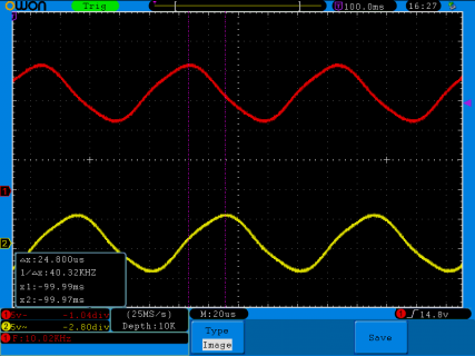
I have tested my QSD by setting up the Si5351 for a 1 MHz detection freq (i.e. 4.0 MHz), and setting Si5351 output 2 for 1.010 MHz. Output 2 is atten by 30 db and fed into the antenna Input. On my scope I see the I/Q signals at 10 KHz and out of phase by almost exactly 90 deg. (i.e. delay is 24.8 us instead of exactly 25.0 us). This seems fine, so I can't reconcile the results I am seeing in your Moseley I/Q phase test.
Here is the scope shot:
20160825_562747.png

Incidentally, how will others be able to compile the program unless they have an audio library with the modified AudioControlSGTL5000.cpp file? My local version is modified of course, as I did this before mentioning it to you.

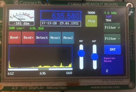
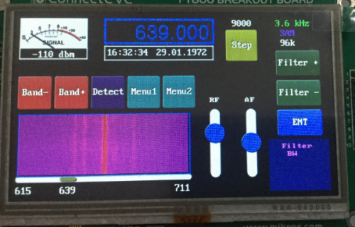
Here is my SDR showing spectrum or Waterfall display. I just need 2 encoders for everything

SDR1.jpgSDR2.PNG

regards Brian
 
Status
Not open for further replies.
Back
Top