2 channel relay - teensy 3.6 digital signal flashing, relay not opening

Status
Not open for further replies.

thomen

Well-known member
Hi All,
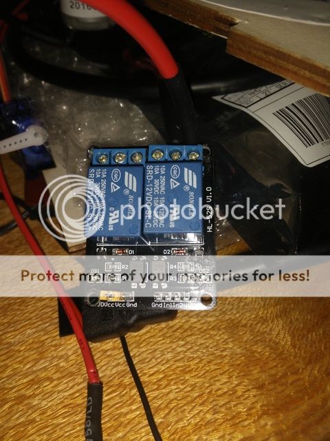
I have a 2 channel relay module.. I have external 5v and gnd hooked up to jdvcc and the gnd on that side and then on the other side I have gnd from the teensy, vcc from the teensy 3.3v (should I hook this up to 5v external?) and then A0 to the in2..

I can see the digital signal light on the relay flashing when I send signal but nothing happens relay wise.. I have 12v external hooked up to NO and then the positive side of a 12v peristaltic pump hooked up to common.. the earth from the 12v pump is hooked up to the 12v external supply..

Any hints? do I need an LLC on the A0 pin to get the relay open?
 
Tell us more about the relay module. Where did you get it, part number etc so we can find more about it to help you out. Attach a (clear) photo of the relay if no other info is available. From what you have told us, It sounds like it does not work directly off the regulated 3.3v from the Teensy. Maybe it is a 5v relay and running on 3.3v is enough to light the indicator only. Whatever you do do not connect 5v or 12v supply directly to the Teensy 3.3v. Apply no more than 5.5v to the Teensy voltage input pin. Never connect external power to the regulated voltage output.
 
Tell us more about the relay module. Where did you get it, part number etc so we can find more about it to help you out. Attach a (clear) photo of the relay if no other info is available. From what you have told us, It sounds like it does not work directly off the regulated 3.3v from the Teensy. Maybe it is a 5v relay and running on 3.3v is enough to light the indicator only. Whatever you do do not connect 5v or 12v supply directly to the Teensy 3.3v. Apply no more than 5.5v to the Teensy voltage input pin. Never connect external power to the regulated voltage output.


Thanks for your reply! Sorry me and specificity again!

So far I tried..

Removing the jumper and connecting 5v from an external source to the vdcc line and external ground on that section too..

I tried a line level shifter on the data line coming from the teensy where the HV and earth were external and the lv and gnd were fed from the 3.3v on the teensy then ran a data line on the dv line to in1 and tried in2 as well..


IMG_20170320_063646.jpg


There's nothing hooked up to the line.level shifter in that shot I moved on and had to unhook it for a sec


Thanks for your reply and help I really appreciate it
 
I can't tell from the picture how 12v current gets to the relay coil. you will have a +5, ground, and control signal on the Teensy side. You will also need 12v and its ground to supply each relay coil. It is likely the 12v and 5v grounds are not common. You will also have the output contacts. The led is most likely just showing the signal lines are turning on the optocouplers and not that the coil has current thru it. The 12v relays will not work on 5v. According to the data sheet they need 75% of rated voltage to just to pull in and for the high sensitivity 12 model in the picture 30 milliamps of current.
 
Last edited:
I can't tell from the picture how 12v current gets to the relay coil. you will have a +5, ground, and control signal on the Teensy side. You will also need 12v and its ground to supply each relay coil. It is likely the 12v and 5v grounds are not common. You will also have the output contacts. The led is most likely just showing the signal lines are turning on the optocouplers and not that the coil has current thru it. The 12v relays will not work on 5v.

So with my wiring I have the ground on the motor going to the ground on the power supply.

I then have the motor + going to the relay common and 12v plus from the power supply going to relay NO

I then removed the jumper and had 5v and ground going to the 3 pin side and the line from the controller on the other side
 
I found your board, its 5 v logic on the optocouplers but for some reason built with 12dc relayYou need to remove the yellow jumper on the left and carefully connect 12v to RY-VCC taking care not to short it to Vcc. You need to make sure the ground from the 12v supply is connected on the same header to the ground pin of the same header. This is my best guess and use at your own risk.
 
Thanks very much I really appreciate that... yes it's super odd..

I'll see if I can get a simpler one that "just works" with 5v and then runs 12v on the other side..
Thanks again for your time and help :)
 
I found your board, its 5 v logic on the optocouplers but for some reason built with 12dc relayYou need to remove the yellow jumper on the left and carefully connect 12v to RY-VCC taking care not to short it to Vcc. You need to make sure the ground from the 12v supply is connected on the same header to the ground pin of the same header. This is my best guess and use at your own risk.

Connections for the motor would probably be 12v to the relay common and them motor + to either NC or NO as you desire and the motor - to ground.

Looks like we were both posting at the same time.
 
Status
Not open for further replies.
Back
Top