I looked at this post an I'm still confused.
https://forum.pjrc.com/threads/32383-Powering-Teensy-3-2-from-external-power-and-still-have-usb-in-with-power-cable-in-it
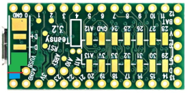
In one place it said to cut the trace to separate USB power from VIN and put a diode from one pad to the middle pad. Teensy 3.2 doesn't seem to have but two pads. In the backside diagram of the 3.2 which is the VUSB pad and which is the VIN? I don't want to waste a board by getting it backward.
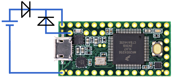
My goal is to run the teensy on USB power while it is connected but have a 4.5V battery source to allow me to save off key data to the EEPROM before having the processor shut itself down via an external mosfet switch inline with the battery V+ feed. In the other post it said to use two diodes one for VUSB to VIN and one for the battery feed to VIN if I understand it correctly. If so which pad gets the anode and which gets the cathode?


