Parts list for MIDI demo board?

Status
Not open for further replies.

mykle

Well-known member
Hi all,

My friend wants me to help him build the PJRC MIDI demo board, made famous here: https://www.pjrc.com/teensy/td_libs_MIDI.html

He picked this because the board design is ready-to-go. All he really wants to do is translate/filter MIDI messages
from the IN port to the OUT port, so even this board is a bit overkill. I already wrote such a thing for USB MIDI on the teensy, so it ought to be straightforward to plug that software into this hardware. But I'm electronically naive, so I have a couple parts questions. When I look up this stuff on Digikey, I'm unsure what to buy:

* I can see the values for the resistors and the caps ... does size matter for those? How many milliwatts can MIDI signals be?
* What kind of diodes should I use in the diode spots? One is a zener, but what specs? And what is the other one?
* Is there a part-number for the specific DIN connectors used?

I'm willing to bet this info is somewhere in this forum, but I can't seem to find it with any of the searches I've tried. Much obliged for any help!
 
Until and unless someone that knows better says differently...

The currents here are very small -- a few mA (that's what the resistors are there to do... limit the current) so 1/4 watt is plenty and the values are also not critical so don't worry about 1% accuracy for these.

Be sure to use the lower values (47ohm) for the out circuit and otherwise follow the text notes if using 3.3 volt Teensy.

The cap is a reservoir cap to smooth the supply voltage - electrolytic caps are standard for this and the symbol is polarized so that's what's intended here. Looks like tantalum in the photo but I don't know how critical it is to have a certain type

The opt-isolator is listed as PC900 (Sharp) but there are a number of similar parts that will work.

There is only one diode as a discrete component - it's a standard signal diode under reverse voltage I believe to protect the opt-isolator if the voltages are reversed. I think any signal diode will work here.

Standard DIN 5 pin (spread across 180 degrees but I've never actually seen the type that is at 240)
 
Last edited:
Thanks! I am starting to pick the parts on Digikey.

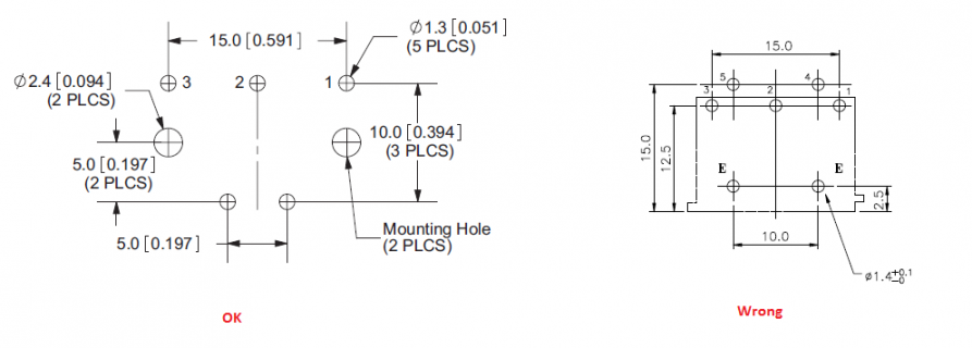
I know the MIDI connector is 180-degree 5-pin DIN (per the midi spec) but I'm not sure which part has leads that will line up with the holes in this PCB design. Is there a standard board footprint for such components? Or do all DIN jacks have the same pin alignment where they meet the board?

On that note: that board has pads for five buttons, and there's five pads per button ... what is the kind of button that fits those pads? (We don't really need the buttons for this project, but, y'know, everybody likes pressing buttons ...)
 
Right... the board. That's also where your zener reference if from...
...The extra diode between the 2 MIDI connectors is a 5.6V zener. Other than this extra diode, the circuit board followed the schematic shown above. The zener diode is not necessary for normal opertation, but does provide extra protection if external voltage is applied to the MIDI OUT port...

But that also answers the spec on it ... 5.6V.

I believe the DIN footprint is pretty standard but check the drawing on the data sheet before you buy.


I've looked at dozens of MIDI schematic images and Paul's is the only one I can find with a reservoir/decoupling cap... so I don't know which role it's meant to fill (or really what the difference is) but I believe the circuit will work with anything type of cap or none at all.

Buttons look like the standard ones Paul sells with the tutorial kit (which would make sense)... they are pretty standard for a larger momentary through-hole ...as long as the pin layout is the same it doesn't matter -- again check the drawings and then the data sheet of any candidate parts before you buy.

I think the big parts are similar to the Sparkfun board's https://www.sparkfun.com/products/12898 (obviously not the SMD stuff!) but Paul's board allows for DIN plugs with the mounting tabs.
 
Last edited:
I built that MIDI test board many years ago. At some point I loaned it out to someone who was working on a MIDI project (at a local Dorkbot meetup), and sadly it was never returned.

So, without the original board and from old info I can piece together, I believe that connector was probably Digikey part CP-7050-ND. But that's a bit of guesswork...
 
...hmmm now that I look around it seems the layout is not so standard... but Paul's part looks correct.
dinfootprint.png
I think the type with the pins all at the back and mounting tabs in the front are more common so watch out.
 
Status
Not open for further replies.
Back
Top