
Good afternoon,
I wrote a simple code with 3 pwm that generates a 0V signal during 55,55us (PWM1) after that 1,5us high and 54us low (PWM2) and finally 2us high and 53,5us low (PWM3) and these three PWMs are repeated non-stop.
A brief explanation of my code. I load a value of the timer at the PIT_LDVAL1 and I wait for the set of the flag at PIT_TFLG1. When the flag is set clear the flag and the timer counts with a new value.
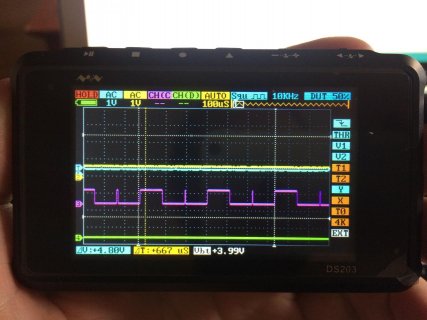
I calculated the values for the PITimer1 in hexadecimal as PWM 1 (55us low), PWM2_1 (1,5us high), PWM2_2 (53us low), PWM3_1 (2us high) and PWM3_2 (53,5us low) with the Teensy at 72MHz, however the high pulses last around 3 and 4 us. For this reason I guess the PITimer1 of my Teensy is working at 36MHz not 72MHz. Why? How can I choose the frequency of the timer? The compiler configures the Teensy at 72MHz, doesn't it? Am I doing anything wrong?
Thanks for the help!.
#include <stdint.h>
#include <mk20dx128.h>
//Number of the pins
#define MOSFET1 13
#define MOSFET2 15
#define MOSFET3 22
#define MOSFET4 23
//Duration of the pulses
#define PWM1 0xFA0 // 55,55us at 72MHz
#define PWM2_1 0x68 // // aprox.1,5us at 72MHz
#define PWM2_2 0xF35 //
#define PWM3_1 0x88 //// aprox.2us at 72MHz
#define PWM3_2 0xF18 //
void setup() {
// put your setup code here, to run once:
//Pins as output
pinMode(MOSFET1,OUTPUT);
pinMode(MOSFET2,OUTPUT);
pinMode(MOSFET3,OUTPUT);
pinMode(MOSFET4,OUTPUT);
//Enable the clock for ports and timers
SIM_SCGC6 |= (1<<24);
SIM_SCGC6 |= (1<<25);
SIM_SCGC6 |= (1<<23);
SIM_SCGC5 |= (1<<13);
SIM_SCGC5 |= (1<<12);
SIM_SCGC5 |= (1<<11);
SIM_SCGC5 |= (1<<10);
SIM_SCGC5 |= (1<<9);
SIM_SCGC5 |= (1<<5);
//Pin 0,1,2,5 of PORTC as GPIO
PORTC_PCR0=PORT_PCR_MUX(0x1);
PORTC_PCR1=PORT_PCR_MUX(0x1);
PORTC_PCR2=PORT_PCR_MUX(0x1);
PORTC_PCR5=PORT_PCR_MUX(0x1);
digitalWriteFast(MOSFET1,LOW);
digitalWriteFast(MOSFET2,LOW);
digitalWriteFast(MOSFET3,LOW);
digitalWriteFast(MOSFET4,LOW);
PIT_MCR=0x00; //PIT on
PIT_TFLG1=0x01;//Clear the flag
}
void loop() {
// put your main code here, to run repeatedly:
PIT_LDVAL1=PWM1; //First value of the timer
PIT_TCTRL1=0x03; //Start PIT1 and interrupts
while(1)
{
/*---------------------------------------------------------------------------
----------------------------------PWM 1--------------------------------------
---------------------------------------------------------------------------*/
PIT_LDVAL1=PWM2_1;//Load a new value for the next pulse
digitalWriteFast(MOSFET3,LOW);
digitalWriteFast(MOSFET1,HIGH);
while((PIT_TFLG1 & (1<<0))==0)
{
//Wait until PIT overflows
}
/*---------------------------------------------------------------------------
----------------------------------PWM 2--------------------------------------
---------------------------------------------------------------------------*/
digitalWriteFast(MOSFET3,HIGH);
PIT_TFLG1=0x01;//Clear the flag TOF
PIT_LDVAL1=PWM2_2;//Load a new value for the next pulse
while((PIT_TFLG1 & (1<<0))==0)
{
//Wait until PIT overflows
}
digitalWriteFast(MOSFET3,LOW);
PIT_TFLG1=0x01;//Clear the flag TOF
PIT_LDVAL1=PWM3_1;//Load a new value for the next pulse
while((PIT_TFLG1 & (1<<0))==0)
{
//Wait until PIT overflows
}
/*---------------------------------------------------------------------------
----------------------------------PWM 3--------------------------------------
---------------------------------------------------------------------------*/
digitalWriteFast(MOSFET3,HIGH);
PIT_TFLG1=0x01;//Clear the flag TOF
PIT_LDVAL1=PWM3_2;//Load a new value for the next pulse
while((PIT_TFLG1 & (1<<0))==0)
{
//Wait until PIT overflows
}
digitalWriteFast(MOSFET3,LOW);
PIT_TFLG1=0x01;//Clear the flag TOF
PIT_LDVAL1=PWM1;//Load the first value to restart the cycle of PWM's
while((PIT_TFLG1 & (1<<0))==0)
{
//Wait until PIT overflows
}
PIT_TFLG1=0x01;//Clear the flag TOF
}
}


I wrote a simple code with 3 pwm that generates a 0V signal during 55,55us (PWM1) after that 1,5us high and 54us low (PWM2) and finally 2us high and 53,5us low (PWM3) and these three PWMs are repeated non-stop.
A brief explanation of my code. I load a value of the timer at the PIT_LDVAL1 and I wait for the set of the flag at PIT_TFLG1. When the flag is set clear the flag and the timer counts with a new value.
I calculated the values for the PITimer1 in hexadecimal as PWM 1 (55us low), PWM2_1 (1,5us high), PWM2_2 (53us low), PWM3_1 (2us high) and PWM3_2 (53,5us low) with the Teensy at 72MHz, however the high pulses last around 3 and 4 us. For this reason I guess the PITimer1 of my Teensy is working at 36MHz not 72MHz. Why? How can I choose the frequency of the timer? The compiler configures the Teensy at 72MHz, doesn't it? Am I doing anything wrong?
Thanks for the help!.
#include <stdint.h>
#include <mk20dx128.h>
//Number of the pins
#define MOSFET1 13
#define MOSFET2 15
#define MOSFET3 22
#define MOSFET4 23
//Duration of the pulses
#define PWM1 0xFA0 // 55,55us at 72MHz
#define PWM2_1 0x68 // // aprox.1,5us at 72MHz
#define PWM2_2 0xF35 //
#define PWM3_1 0x88 //// aprox.2us at 72MHz
#define PWM3_2 0xF18 //
void setup() {
// put your setup code here, to run once:
//Pins as output
pinMode(MOSFET1,OUTPUT);
pinMode(MOSFET2,OUTPUT);
pinMode(MOSFET3,OUTPUT);
pinMode(MOSFET4,OUTPUT);
//Enable the clock for ports and timers
SIM_SCGC6 |= (1<<24);
SIM_SCGC6 |= (1<<25);
SIM_SCGC6 |= (1<<23);
SIM_SCGC5 |= (1<<13);
SIM_SCGC5 |= (1<<12);
SIM_SCGC5 |= (1<<11);
SIM_SCGC5 |= (1<<10);
SIM_SCGC5 |= (1<<9);
SIM_SCGC5 |= (1<<5);
//Pin 0,1,2,5 of PORTC as GPIO
PORTC_PCR0=PORT_PCR_MUX(0x1);
PORTC_PCR1=PORT_PCR_MUX(0x1);
PORTC_PCR2=PORT_PCR_MUX(0x1);
PORTC_PCR5=PORT_PCR_MUX(0x1);
digitalWriteFast(MOSFET1,LOW);
digitalWriteFast(MOSFET2,LOW);
digitalWriteFast(MOSFET3,LOW);
digitalWriteFast(MOSFET4,LOW);
PIT_MCR=0x00; //PIT on
PIT_TFLG1=0x01;//Clear the flag
}
void loop() {
// put your main code here, to run repeatedly:
PIT_LDVAL1=PWM1; //First value of the timer
PIT_TCTRL1=0x03; //Start PIT1 and interrupts
while(1)
{
/*---------------------------------------------------------------------------
----------------------------------PWM 1--------------------------------------
---------------------------------------------------------------------------*/
PIT_LDVAL1=PWM2_1;//Load a new value for the next pulse
digitalWriteFast(MOSFET3,LOW);
digitalWriteFast(MOSFET1,HIGH);
while((PIT_TFLG1 & (1<<0))==0)
{
//Wait until PIT overflows
}
/*---------------------------------------------------------------------------
----------------------------------PWM 2--------------------------------------
---------------------------------------------------------------------------*/
digitalWriteFast(MOSFET3,HIGH);
PIT_TFLG1=0x01;//Clear the flag TOF
PIT_LDVAL1=PWM2_2;//Load a new value for the next pulse
while((PIT_TFLG1 & (1<<0))==0)
{
//Wait until PIT overflows
}
digitalWriteFast(MOSFET3,LOW);
PIT_TFLG1=0x01;//Clear the flag TOF
PIT_LDVAL1=PWM3_1;//Load a new value for the next pulse
while((PIT_TFLG1 & (1<<0))==0)
{
//Wait until PIT overflows
}
/*---------------------------------------------------------------------------
----------------------------------PWM 3--------------------------------------
---------------------------------------------------------------------------*/
digitalWriteFast(MOSFET3,HIGH);
PIT_TFLG1=0x01;//Clear the flag TOF
PIT_LDVAL1=PWM3_2;//Load a new value for the next pulse
while((PIT_TFLG1 & (1<<0))==0)
{
//Wait until PIT overflows
}
digitalWriteFast(MOSFET3,LOW);
PIT_TFLG1=0x01;//Clear the flag TOF
PIT_LDVAL1=PWM1;//Load the first value to restart the cycle of PWM's
while((PIT_TFLG1 & (1<<0))==0)
{
//Wait until PIT overflows
}
PIT_TFLG1=0x01;//Clear the flag TOF
}
}
 riority(newpri).