Line in voltage of Teensy

Status
Not open for further replies.

Mfive

Member
Issues concerning line in/out voltage of Teensy audio shield

My two questions pertains to the line in/out of the Teensy audio output.

Firstly, I am building a project that consists of a raspberry pi zero (modified for digital pin audio output shown in reference image attached) connected to the line in of Teensy audio shield(modified for quad output as shown in the reference image). The audio shields seems to be recieving the sounds from the raspberry. However, when testing both audio shields, I noticed the top audio shield which is recieving the line in from the raspberry has reduced quality of audio. I was wondering whether I might have potentially damaged my audio shield because of lack of familiarity with the line in/out voltage. I used a mulitmeter and measured the output from the raspberry zero to be 0.68V which I think is ok for the Teensy audio shield. However. I am still wondering whether I might be inadvertently damaging my audio shield by connecting it in this manner to my raspberry?
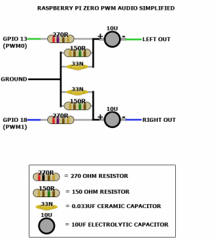
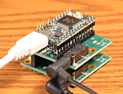
gYXyuT1.pngteensy3_audio_quadch.jpg

Secondly, I then connected the line output from the Teensy audio shield to the adafruit 3G shield (shown in image below). Since the line out voltage from the audio shield is very low, I thought that this setup would be ok. I tested it for the first time with QuadChannelOutput.ino example and it worked with the music being transmitted over the phone. However, when I tested it today, it now seems that the microphone on my 3G shield could be damaged (picking up only buzzing sounds when I worked fine previously). I then disconnected the audio shield and used a simple 3G shield test and did a voice call to another phone, but the microphone of the 3G shield remains impaired. I was wondering for this case as well, whether I might have got the audio line out set up wrong (from the Teensy audio shield) causing an overvoltage to the 3G shield microphone, or could it be that the loud volume of the music (ie. QuadChannelOutput.ino wav files output) be the damaging source?
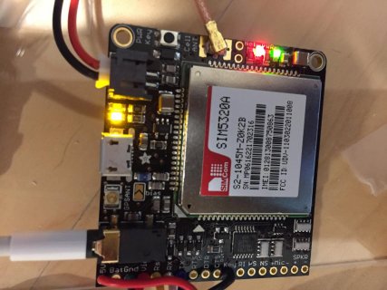
Photo 3-4-17, 7 48 36 pm.jpg
 
Last edited:
A true microphone input will not like line audio, being intended for a much lower input with a preamp, and quite possible DC bias for the mic. The capacitors in series with line in and line out should have tamed that but is not impossible it's bias circuit took a hammering somwhere along the way and you don't have a working pre-amp any more.

Edit: looking at
https://cdn-learn.adafruit.com/asse...iginal/adafruit_products_schem.png?1440185454 indicates there is nothing between the mic in pins and the main IC so no easy method to skip pre amp or anything, which limits options here, unless the data sheet gives options for changing the mic function to line in.
Edit edit: https://cdn-shop.adafruit.com/datasheets/SIMCOM_SIM5320_ATC_EN_V2.02.pdf gives the AT commands about page 250- you can change the gain of the mic, but do not appear to be able to turn bias on/off or fully bypass the preamp - dropping the gain to zero may improve things or may not.
Edit Edit Edit: https://cdn-shop.adafruit.com/datasheets/SIM5320_Hardware+Design_V1.07.pdf page 30 gives the mic specs. It's applying 1.1 volt bias and max rated current is 1mA.

Thanks for your reply. If I connect from the audio shield's headphone port (instead of line out) to the microphone/headphone port of the 3G shield, would that be a better idea?
 
Very much no, since the headset amp is not referenced to 0 volts and doesn't have DC blocking caps. Suspect some impedance matching is required to get line current/voltage combo matched to the needs of a circuit intended for an electret mic. Signal types are very much different but probably don't matter enough that things like
http://www.epanorama.net/circuits/line_to_mic.html
Will work - see the one for use with electret mics, noting that the cap is already present on the board so you just need the resistive divider. What may also have been a problem is you would have grounded one of the mic lines to connect it. Reading the data sheet it's intended to be a balanced line that free floats. Proper solution would be a balun (small transformer) unsure if a second DC blocking cap on the second mic line will get close enough to get that phone module happy.
 
For connecting from the raspberry audio out circuit to the Teensy audio board, would it be worth trying to connect both via an (audio) attenuator to prevent damage to the audio board?
 
If you are going to the line in, should be fine though you may find the level is high enough to cause clipping if gain on that end is too high. Key thing is the line in pins have DC blocking caps which keeps things simpler. Do check on the Pi forums for any gotcha's with level or grounding around them but I think they are reasonably flexible. Adding attenuation may be needed for maximum quality but don't think the Pi audio out is going to be high enough level to actually damage the line in. Remember the phone module input is probably fine, it's the pre-amp intended for a very weak mix signal+DC bias that killed things.

One thing to check before doing anything is that gnd on the Pi and gnd on the Teensy are the same. Depending on your power supplys there may be excitingly amounts of voltage between them that need to be managed
 
Thanks for your advice. I just tried to use line out from the audio board to the phone module, however, the volume from the Pi zero is too soft even after setting the highest volume on both Pi and Teensy. I then tried to use two amplifiers, TPA2016 and MAX9744 to boost the line out. However, either failed to amplify the volume audible enough to be heard over the phone microphone input. I confirmed the low volume by connecting the amplifer outputs to a pair of earphones and then directly listening through them. (Using the SD card test QuadChannelOutput.ino however still gave good volume output suggesting that the low volume is a result of from the Pi zero audio circuitry. That being said, the Pi zero audio output is audible enough for a pair of directly connected earphones).

With the amplifer option exhausted, now I am contemplating using the headphone port of the audio board and connecting that to the phone mic input. However, I note that you advised against it previously. I was wondering if I were to pursue this method, is there a way for me to install some protective mechanism (eg. capacitors, diode, resistors) to shield either or both the audio boards and the phone module when connected together?
 
Last edited:
Looks like the Pi audio out is a bit interesting:
https://learn.adafruit.com/introducing-the-raspberry-pi-zero/audio-outputs

Note that it's got DC blocking caps on it's output already so there's going to be attenuation there from have DC caps at both ends. You could try bypassing the Teensy audio board caps, but that has it's own excitement potential. Other option is to put an op amp on the Pi output side to try for a bit of bias and gain adjustment to get it closer to what the audio board is expecting. Also, have you tried tweaking the line in setting
from the audio gui:
______________________________________________________________
lineInLevel(both);

Adjust the sensitivity of the line-level inputs. Fifteen settings are possible:

0: 3.12 Volts p-p
1: 2.63 Volts p-p
2: 2.22 Volts p-p
3: 1.87 Volts p-p
4: 1.58 Volts p-p
5: 1.33 Volts p-p (default)
6: 1.11 Volts p-p
7: 0.94 Volts p-p
8: 0.79 Volts p-p
9: 0.67 Volts p-p
10: 0.56 Volts p-p
11: 0.48 Volts p-p
12: 0.40 Volts p-p
13: 0.34 Volts p-p
14: 0.29 Volts p-p
15: 0.24 Volts p-p

_________________________________________________________________

Basic problem here is that neither the Pi nor the phone module were really designed to work with other devices and simplified their design to just what was needed. Depending on what you are actually trying to do, would making the Teensy an USB audio device and getting the audio out of the PI digitally get where you need to go? Makes reprogramming tricky.
 
Thanks, I have tried those GUI settings but they dont make a difference to the line out output. I thus went aheead to use the headphone port. The audio out from the headphone port of the Teensy audio board to the phone module mic input works..at least for now *fingers crossed*. I then decided to add a DTMF board (to read tones from the phone module) and connect that to the TRRS adapter at the input of the phone module. However, such a connection means that the audio output from the Teensy board and the audio input to the DTMF shield shares the same GND connection on the TRRS. When on shared GND connection, either dont work (alot of strange noises but no appreciable audio). When the DTMF or Teensy board audio connections are used separately from each other (ie. GND connection not shared), they work.

In view of this, I am now wondering if there is a way to allow shared GND connections. I am thinking of using two relays such that the GND connections between the DTMF module and the phone module is servered when the Teensy audio board is in use and vice versa for the GND connection between the Teensy audio baord and the phone module. That way I dont have to always physically insert and remove the respective GND connections. What do you think of this method Gremlin Wrangler? And if this methid is feasible, what kind of relay should I be getting? I have used solid state relays for DC loads before, but a relay that allows the kind of low load voltages between audio ports is not something I am familiar with.
 
Last edited:
re the line settings they certainly should have made a difference at least making the replay of the lineIn signal weaker. No change suggest other things at play.

As noted above and on the product page the Teensy headset jack is not gnd referenced, so you really can't connect it to anything that isn't isolated. Using relays isn't a good idea since that'll have effective gnd voltages bouncing all over the place and a very complex power supply arrangement with independent isolated feeds. You need to isolate both halves of the headphone signal, either using DC blocking capacitors or an audio isolation transformer.
https://www.pjrc.com/store/audio_ground_isolator.html is one, but also available elsewhere via whatever source works for you.

It's also possible you could have the Teensy decode the DTMF tones via FFT, though since you have already paid for the module might as well use it since it skips some decoding steps.

Do be aware that after all of this that your audio board, DTMF and phone module have all seen a lot of abuse and probably at least one will suffer an early death. If this is a fun project in the house that's fine but if the aim here is to stick it on a mountain somewhere then you need to consider locking down a working design and then building it out with new parts that haven't had excessive currents punched through them in strange directions.
 
Thanks for your recommendation. My project is in house but I will still check out the audio isolation transformer solution, hopefully that will stop the humming noise. With that in place, would that resolve the issue of potentially damaging circuit to either one of those three components? Or would that issue persists as long as the Teensy audio board is used to connect to the phone module?
 
the isolation will greatly reduce the potential for problems, since it keeps the headphone and it's ungrounded balanced drive away from the phantom power the mic in the phone module is trying to drive which was on the list of problems. Will add another layer of attenuation but will hopefully help keep everything else sane.
 
Status
Not open for further replies.
Back
Top