Detecting 120VAC with Teensy

Status
Not open for further replies.

gfvalvo

Well-known member
Hi All.

I need a simple circuit to allow a micro-controller to detect if 120VAC power is present. Fast turn on / turn off isn’t that critical, just reliable detection, preferably using a digital input rather than an analog one.

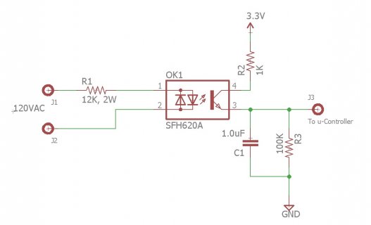
I'm thinking of the circuit in attached jpg. My goal is to saturate the transistor during its ‘on’ time so that the voltage across C1 rises to a solid logic High as it charges. During the portion of the 60 Hz cycle where the transistor is off, the time constant of C1 / R3 should prevent the output from sagging too much.

When the 120VAC goes away, it might take a time constant (C1/R3) or a little longer for the output to drop below Vin-low-max for the Teensy. That doesn’t matter for my application.

Appreciate any thoughts from those who have done this before.

Thanks.
Opto.jpg
 
why not have a 120VAC relay (shneider for example) that when triggered it closes an isolated contact, and use that to tell the teensy that there is power... it's really the simplest
 
Thanks for the reply. Do you have a pointer for a reasonably-sized, reasonably-priced device? I don’t need contacts that can control an air conditioner, just a few micro amps to drive a digital input.
 
the schneider ones used in gate systems work well. you can get timer and non timer ones, and they support ranges from 24AC to 240AC

I use them when I wire up 3 phase 600volt gate systems, to control the control box, switches, and access systems

Local prices usually are around 20$ cash. But really, you should be able to use any 220vac relay just fine, the schneider one is just more for commercial/industrial use

Tony
 
That’s one solution if I can find something appropriately sized. Using an industrial-sized product to control a logic level offends my sense of proportion.
 
true, but when working with 3 phase 600volt systems, and using those relays to "close contact" for 12v DC access card systems like KANTECH, and automating the logic of the control board's controls circuits which flow 24V AC through the contacts, it's actually safer :p
 
I have been playing around with using current sensors to detect when well is on...
https://www.sparkfun.com/products/11005

Sometimes wonder if it would be bad to instead just setup a wall wart to convert to +5v, have small load to bleed it off and then just connect it up to an IO pin...
 
yeah, pretty sure those square apple phone chargers are small. although, pretty sure relays in 120VAC can be that small too:p
 
So far, still liking the opto solution the best. Guess I'll order a few a play with the component values.
 
Last edited:
Normal circuit to tame an 220 into an LED includes a cap in series, along with the current limiting resistor Google fu is not helping me find the relevant math at the moment to size the cap and resistor to get the right diode current. Basic idea is that the cap charges across each zero crossing interval, and while charging provides current to LED + resistor at reasonably sane voltage, avoiding need for massive power resistor to dump the heat.

This does mean the LED will pulse, which will need to be managed in the software with counters or interupts rather than just polled.

It's also recommended to look at anti tracking slots, good strain relief, double insulation and similar excitement reduction features if you have 220V anywhere near the Teensy 3.3V
 
Use a half wave rectifier to drive an opto isolator / relay of your choice. Then double check your isolation/grounds like GremlinWrangler suggests.
 
Normal circuit to tame an 220 into an LED includes a cap in series, along with the current limiting resistor
I had considered that. The ~1.2W burned in the power resistor was on the verge of causing me to include the series capacitor.

The phenomenon is reactance. It’s the imaginary component of complex impedance. For a capacitor, the formula is 1/(j*2*pi*F*C).

So, 0.25uF in series with a 5.6K resistor would give an impedance magnitude (phase doesn’t matter here) of ~12K. This provides the same current through the LED as 12K resistor alone, but the power dissipated in the resistor drops to ~0.56W. On the down side, I now have to include a capacitor rated at say 300VAC for adequate margin.

The LED will pulse with capacitor present or not. It’s being driven by AC. The RC filter on the output is meant to smooth that out so the software doesn’t see it.

The diode anti-parallel to the LED should obviate the need for half-wave rectification. Even better if the opto contains anti-parallel LEDs. Then there is light on both halves of the AC cycle.

BTW, the application is 120VAC, not 220. But the safety points are still well taken.

Thanks.
 
Last edited:
If you half wave rectify first, you'll need a lesser optoisolator (without said antiparallel), and you can smooth before the optoisolator - not after, meaning a constant DC signal to the teensy without any more filtering.
dia.png

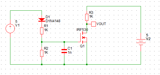
I haven't bothered to change any of the values but that should give you the jist. You might be ok with a mosfet you might not, I however do not have a schematic part for an opto isolator!
 
Yeah, those values would be a bit exciting as written, and as wired leaves things energised at your neutral potential. Which may not be the same as earth. @Edward, have done a schematic opto by parking an LED beside an LDR before.
 
I accept that I have been lazy and omitted to address the ground!
Actually, that was my first though, but simmetrix (the simulator I use) doesn't have a proper LED symbol.

I do feel the schematic illustrates the point though :p
 
Sometimes wonder if it would be bad to instead just setup a wall wart to convert to +5v, have small load to bleed it off and then just connect it up to an IO pin...
So, I did a little simulation of the various techniques. I'm think both the half-wave rectifier and capacitive voltage divider+opto ideas could be made to work. Then, I had an epiphany:

Cost of digging an old wall wart out of my junk box and using it as Kurt suggested: $0.00

Cost of part for any other implementation: more than $0.00

Done, thanks.
 
walwart will work fine IF the voltage doesnt vary or out of range, not properly matched with labeled. Lots of them are unregulated. You should test out the voltage, as teensy 3.5 cannot exceed 5volts and teensy 3.6 cannot excees 3.3volts, an unregulated chinese wallwart can fry them if your using them as inputs, you should still use optocoupler this route and you can use a wider range of adaptor then.

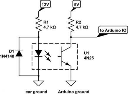
ex, 120v AC to 12v DC adaptor can probably show 13-14Volts, or 11, who knows, but 1.5Kohm resistor series to optocoupler with a flyback diode then to MCU from other side of opto is more ideal.
ignore the 4.7K resistor in pic, should be 1.5K

lp5m2.png
 
Last edited:
Can also probably come up with resistors for a voltage divider that will bring the level to between Vih(min) and 3.3V for the entire range of possible 5V wall wart output levels.
 
I do feel the schematic illustrates the point though :p

That schematic illustrates the point that if you accidentally cross your hot and neutral wires on the 120V side, you will poke 120V into your digital circuitry.
Always, always, always use isolation when working with mains. Always. Opto-couplers, sense transformers, or, worst case, a bridge rectifier. You don't want your digital ground to be riding up and down the hot phase.
 
Status
Not open for further replies.
Back
Top