PROBLEM w/ Multiple analogreads on teensy 3.5

Status
Not open for further replies.

gwk21

Active member
Hello,

I'm currently in the process of building an external controller with quite a few potentiometers and switches. I'm using a teensy 3.5 and have 22 potentiometers connected to analog pins and 11 switches connected to the digital pins all of which are to be read within MaxMSP. My problem is that while the pins on the board are being read and can be seen to be active within the serial monitor, they aren't responding at all when I actually turn a potentiometer or flick a switch. I'm using a sketch by Thomas Ouellet Fredericks that is specifically for arduino and MaxMSP communication (As shown below) and I previously tested this set up on a slightly smaller scale (8 potentiometers and a few switches) with a teensy 2.0 ++ board and everything worked absolutely fine. I was hoping that by changing the code slightly to suit the 3.5 board everything would be working as expected but that's not the case. Any help on this would be seriously appreciated, I'm a bit of an amateur and perhaps got ahead of myself but I'd really like to see this working!

- I'm confident the cable is good
- I'm certain all the wires are in their right places
- I've looked into reading the sensors twice but had no luck
- Along with the traffic/wild values everything appears to just stop after a few minutes

Code below:


/*
* Arduino2Max
* Send pin values from Arduino to MAX/MSP
*
* Arduino2Max.pde
* ------------
* This version: .5, November 29, 2010
* ------------
* Copyleft: use as you like
* by Daniel Jolliffe
* Based on a sketch and patch by Thomas Ouellet Fredericks tof.danslchamp.org
*
*/


int x = 0; // a place to hold pin values
int ledpin = 13;

void setup()
{
Serial.begin(115200); // 115200 is the default Arduino Bluetooth speed
digitalWrite(13,HIGH); ///startup blink
delay(600);
digitalWrite(13,LOW);
pinMode(13,INPUT);
}


void loop()
{

if (Serial.available() > 0){ // Check serial buffer for characters

if (Serial.read() == 'r') { // If an 'r' is received then read the pins

for (int pin= A0; pin<=A22; pin++){ // Read and send analog pins 0-21
x = analogRead(pin);
sendValue (x);
}


for (int pin= 0; pin<=10; pin++){ // Read and send digital pins 0-11
x = digitalRead(pin);
sendValue (x);
}

Serial.println(); // Send a carriage returnt to mark end of pin data.
delay (5); // add a delay to prevent crashing/overloading of the serial port

}

}
}

void sendValue (int x){ // function to send the pin value followed by a "space".
Serial.print(x);
Serial.write(32);
}


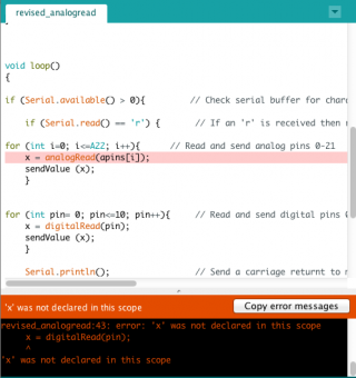
Screen Shot 2017-04-17 at 09.50.25.png
 
The problem is that the PIN mapping of the analog pins A0 to A22 is not linear. As you can see in pins_arduino.h A0 to A9 are defined consecutively:
Code:
#define PIN_A0  (14)
#define PIN_A1  (15)
#define PIN_A2  (16)
#define PIN_A3  (17)
#define PIN_A4  (18)
#define PIN_A5  (19)
#define PIN_A6  (20)
#define PIN_A7  (21)
#define PIN_A8  (22)
#define PIN_A9  (23)
So that your loop would physically go correctly through pins 14 to 23 and everything works as expected. But for the higher analog pin numbers, they aren't consecutive:
Code:
#define PIN_A10 (64)
#define PIN_A11 (65)
#define PIN_A12 (31)
#define PIN_A13 (32)
#define PIN_A14 (33)
#define PIN_A15 (34)
#define PIN_A16 (35)
#define PIN_A17 (36)
#define PIN_A18 (37)
#define PIN_A19 (38)
#define PIN_A20 (39)
#define PIN_A21 (66)
#define PIN_A22 (67)

Thus your loop "for (int pin= A0; pin<=A22; pin++)" does run from pin 14 to 67 which explains the weird result which you see. You should define an array of the analog pins which you want to read, first, (before setup) and then later loop through that array:
Code:
uint8_t apins[] = {A0, A1, A2, A3, A4,...and so on..., A21};
void setup() {
...
}
void loop() {
  for(int i=0; i<22; i++){
    x = analogRead(apins[i]);
    sendValue (x);    
  }
}
 
Ah yes that does make sense!

I've implemented the code you shared but I am now getting an analogread error message regarding 'x' (See attached below)

Is this because the code for the digital pins has to be changed also to work in conjunction with this new defined array?

Apologies if this is trivial stuff but this is the first time i've encountered this problem.

Thanks again for the speedy response!

Screen Shot 2017-04-17 at 14.55.02.png
 
Did you accidentally delete the line
Code:
int x = 0; // a place to hold pin values
before setup? I didn't mention it explicitly since it was clear for me that it would remain there. You never can use a variable in C/C++ if it has not been declared in the correct scope before...

The digital pin stuff may remain as is.
 
Last edited:
Ah yes I must have deleted by mistake, thank you.

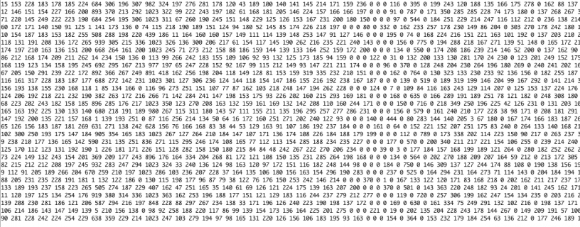
It looks like all the analog pins are now being recognised so that definitely helped, but I'm still faced with this constant fluctuation...

Would you have any other ideas on what the problem may be?

Screen Shot 2017-04-17 at 15.45.56.png
 
Yes, I probably have. Unfortunately, you neither posted pictures of your wiring, nor a schematic. But I guess that you
1.) didn't read well the Teensy reference manual which stated that the varying input impedance of the analog pins (due to the switched delta-sigma-conversion) requires potentiometers between 5k and 10k, higher values will give unstable readings and that there should be a 10nF capacitor between each analog pin connected to the wiper of a potentiometer and ground.
2.) didn't connect the ground pins of the potentiometers to the AGND pin of the Teensy
3.) didn't add a 10uF capacitor between the hot pin of the first potentiometer (which should be connected to 3.3V) and GND

You should add the potentiometers one by one while connecting the remaining analog pins to AGND, check the readings, and the corresponding voltage levels with your oscilloscope. And only add the n-th potentiometer after all others from 1 to n-1 are working correctly. That's systematic electrical engineering!
 
Last edited:
1. try bringing one of the analog pins to Ground or to 3.3v and see if your output reflects those values for that pin
2. you are reading (digitalRead) pins 0 to 10, but you MUST do a pinMode(xxxx,INPUT); in setup() for each of those pins.
for(int i=0;i<11;i++) pinMode(i,INPUT);
you could pull one of those to ground or 3.3v and confirm output changes
3. use voltmeter to measure output from pots
4. your sketch suggests 23 +11 values per line, but your sample output has many more values per line??
5. cosmetic, need pinMode(13,OUTPUT);

This variation of your sketch works for me. Tested by pulling various pins to ground or 3.3v
Code:
int x = 0; // a place to hold pin values
int ledpin = 13;
uint8_t apins[] = {A0, A1, A2, A3, A4, A5, A6, A7, A8, A9, A10, A11, A12, A13, A14, A15, A16, A17, A18, A19, A20, A21, A22};
void setup()
{
  Serial.begin(115200); // 115200 is the default Arduino Bluetooth speed
  pinMode(13,OUTPUT);
  digitalWrite(13, HIGH); ///startup blink
  delay(600);
  digitalWrite(13, LOW);
  pinMode(13, INPUT);
  for (int i = 0; i < 11; i++) pinMode(i, INPUT);
}


void loop()
{

  if (Serial.available() > 0) { // Check serial buffer for characters

    if (Serial.read() == 'r') { // If an 'r' is received then read the pins

      for (int pin = 0; pin <= 22; pin++) { // Read and send analog pins 0-21
        x = analogRead(apins[pin]);
        sendValue (x);
      }


      for (int pin = 0; pin <= 10; pin++) { // Read and send digital pins 0-11
        x = digitalRead(pin);
        sendValue (x);
      }

      Serial.println(); // Send a carriage returnt to mark end of pin data.
      delay (5); // add a delay to prevent crashing/overloading of the serial port

    }

  }
}

void sendValue (int x) { // function to send the pin value followed by a "space".
  Serial.print(x);
  Serial.write(32);
}
 
Last edited:
I'm aware of the impedance and yes the potentiometers are 10k, however I was under the impression that using capacitors simply aided smoothness of the signal but isn't completely necessary? As mentioned before I had used this set up on a smaller scale with another teensy board and it worked fine. But perhaps the 10uF capacitor between the primary potentiometer and GND is necessary?

I did think I was pretty thorough in my testing but apparently not! I think you're right and i'm going to re-wire from scratch and hopefully it's something minor within the wiring setup.

Thanks again for the help, I'm sure you can expect another post once i've gone over the wiring again...
 
@manitou

Thanks also for this the suggestions and this revised code however this sketch doesn't seem to work for me.

I'm going re-wire and go over everything and yes do as you suggest and see if the output reflects the values for the individual pins.
 
The teensy 2 is 5v based, the T3.5 is 3.3v. Are you running pots at 3.3v with the T3.5? T3.5 analog will only measure 0 to 3.3v, and some analog pins are NOT 5v tolerant. A photo of your setup might help. How does voltmeter reading of a pot compare with analogRead() of the that pot?
 
Yes I've made sure to run the pots at 5v for the 2 and 3.3v for the 3.5. Theres not much of a setup to show as I took everything apart yesterday to try and resolve the issue, but simply connecting a single pot (middle pin to A0 and left and right to ground and power) doesn't work. As mentioned before I've done the same process with the 2.0 but as this uses a mini USB and the 3.5 uses a micro and the fact that all is working well with the 2 I'm considering the possibility that it may just be a dud cable? I'm not sure how to assess the cable situation as I've not encountered this before and i'm able to reboot the 3.5 via the onboard button and the serial monitor does recognise the board but just can't seem to process parameter changes? Very confused...
 
"doesn't work" -- what does that mean? if you take A0 to ground, what does analogRead(A0) return? and A0 jumpered to 3.3v? what does voltmeter on your pot say? you also said my variation of your sketch "doesn't seem to work", what does that mean? that sketch should run and print something even with nothing connected to any of the pins.
 
Sorry I realise I'm not being very clear i'm still fairly new to all of this. As far as your sketch not working, unlike other sketches it doesn't communicate to my MaxMSP patch for some reason.

However, a new development....

I've just reset my computer and now the the pot value changes are being recognised...I have literally no idea why this has just started happening. BUT when using the 3.5 with a breadboard it does not work so now I think i'm missing something incredibly obvious with the breadboard setup which i'm hoping is an easier fix.

The only possible things I can think of which I may not be aware of are:

1) I'm connecting the power and ground from the power supply to the boards 3.3v pin and GND pin, but there is a GND, GND and an Anlog GND as well as two 3.3v pins, I've tried each of these but am I missing something painstakingly obvious here?

2) I'm using a 12v power supply to run the breadboard power supply and although it states that 12v should be fine I've had old keyboards/synths in the past that suggest for example 9v-12v but don't actually like 12v. I feel i'm clutching at straws here but I'm just perplexed.

Sorry I realise this is probably incredibly trivial for a lot of you but i'm still learning.
 
You are't really clear...

Step 1: Since you are designing a circuit, you should have made drawings/schematics before building (at least, that's the correct and systematic way). Post these here for double checking.

Step 2: Take high-res pictures from your breadboard wiring, so that others here might check if that corresponds to the schematics.

I'm pretty sure that we will find a simple power supply or grounding problem. But let's do things step by step. Schematics first.
 
I did not previously draw up schematics, I researched the possible ways to approach my project and got it working on a smaller scale with the teensy 2, my background is in visual programming languages so the world of building physical circuits and arduino is still unfamiliar.

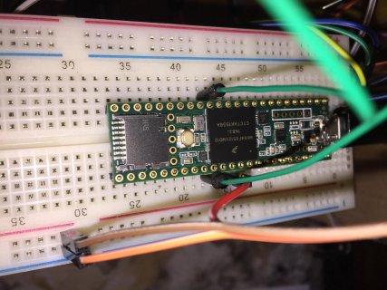
I've attached some photos below and just in case it's not clear this is for a single potentiometer with the middle pin (RED) connected to the A0 pin on the board and the outer pins (BROWN & ORANGE) connected to the breadboard power and ground which are connected to the boards 3.3v and GND pins.

Here's hoping i've just been staring at this for too long and missed something obvious..


IMG_1109.jpgIMG_1276.jpg
 
There is something very obvious and now I understand why that is not working: YOUR PIN HEADERS OF THE TEENSY ARE NOT SOLDERED!!! THAT CAN'T WORK!!!

oh man... there is no warranty that every pin header has contact in the Teensy's holes if they aren't soldered.

Second... You power the Teensy from USB AND from the board supply. That risks to fry things. Either the one or the other.
 
Last edited:
There is something very obvious and now I understand why that is not working: YOUR PIN HEADERS OF THE TEENSY ARE NOT SOLDERED!!! THAT CAN'T WORK!!!

Yep, that's the worst. Though you appear to have both USB power and power to 3.3v. That could be a problem that could cause damage? maybe do away with the 3.3v feeds, keep the common ground to your other power supply that feeds 3.3v to external devices. i'm not the one to give electrical advice :)
 
@manitou I did consider this yes, however I only started to use the power supply as when I left it simply to USB power the board kept disconnecting due to "too much power being drained from my computer" maybe I should look into your suggestion though.
 
I better get the soldering iron out then..

of course it was something as obvious as that...

Thanks a lot for the help guys, really appreciate your time. I'll solder up the pins and hopefully things start to go more smoothly!
 
Status
Not open for further replies.
Back
Top