wiring sensors teensy 3.6

Status
Not open for further replies.

rok

Member
Hi all,
Is it the correct way to wire 12 x A1318 hall sensors http://www.allegromicro.com/~/media/Files/Datasheets/A1318-A1319-Datasheet.ashx?la=en&hash=FE0C31055C84B8E8C655FE86A6963B0D82BCC37E and one rotary encoder?

A9 to A11 are suppose to be connected also. as for gnd 2 to each sensors and 3V3.

The A1318 draws 7mA each so I suppose it is ok to use the 3V3 output from the teensy.
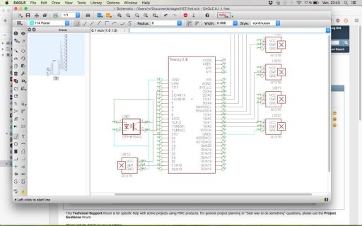
Capture d'écran 2017-05-05 22.43.50.jpg
 
Depends on the application but you may find the useful range of values is pretty low from the sensors without doing some signal conditioning, suggest some testing with at least one device to confirm, unless you happen to know how many Guass you will have in your final design already. Otherwise you would need to add a preamp to boost the signal a bit. Though if it's just a little boost on the range you need using a lower voltage reference on the ref pin or setting aref to internal (1.2V) would give a bit more headroom at the cost of making other analog inputs work a bit differently if added later.

Your wiring on the encoder depends a lot on the data sheet for the item. The data sheet for the part in your schematic is an optoisiolator, where I think you are planing to use an optical position sensor aren't you (rotary encoders are normally mechanical)? If it's as simple device you may need to add a series resistor with the LED and a pulldown to the pin, either with pinMode or externally.
 
Thanks!

I have estimated the gauss value of the two types of magnets I want to detect should be between 100 and 300 gauss. I have used this for the calculation https://www.kjmagnetics.com/calculator.asp

The A1318 provides 2.5mV/G so I should get between 0,25V and 0,75V. Otherwise I could change to A1319 witch double this values. so 0,5 to 1,5v. Maybe a better option?

In the end in my code I want to set two thresholds, one around 100 gauss and the other around 300. so the linear part of the sensor is only important to have the useful range of detection.

Do you have a link to a more detailed explanation of what changing the aref values helps for?

for the encoder I am trying to use one scavenged from a printer. It comes on a board with a few smd caps and resistors. I will send a photo soon.
 
With those values you should be able to get a reasonable read. default range =1024 at 3.2V so lsb = 00.3V so your 0.5v difference between low and high gets you 166 steps which should work even though that signal will have a fair bit of noise. Changing the Aref value changes the value the ADC compares your input to. So if you know you won't get more than 1.2V (or at least won't need to know more than 'it's high') you can set that https://www.arduino.cc/en/Reference/analogReference (note values are default Arduino, not teensy but commands are the same). That means in the above calculation 1024 is 1.2, so 0.0011 V per LSB so 0.5V delta will be 500 steps and therefore much easier to pick apart if with some noise in the values. This also makes some noise types larger as well so you are still better off if absolute precision required using high performance op amps to condition your signal to match a higher value ref voltage, but where simple design and reasonable part count using the raw ADC should work ok.

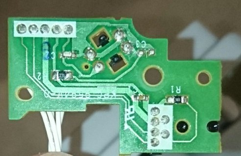
Re the board, posting a photo won't help much. Would be better if you can do a basic trace of the board and the components since you are the only one who can flip it back and forth to see what's going on, and apply the meter to confirm. From the sounds if it though it's not an all in one device so some supporting components will be needed. though you can probably use the existing board for that possibly with some resistors changed for 3.3V.
 
ok thanks a lot your explanations are very clear.
I will go for the A1318 then as I might need some extraprecisions in other applications. For my first project it will be enough with the aRef trick you explained.

I will investigate the board and come back with more info. Thanks.
 
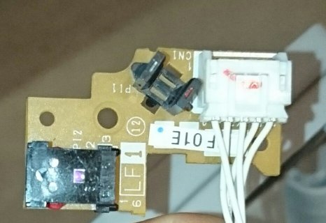
So here is the board :
_20170507_233214.JPG
_20170507_233241.JPG

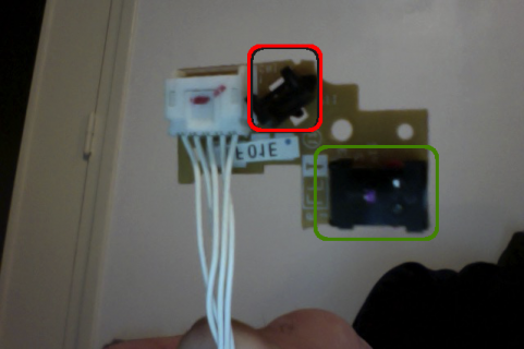
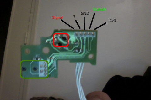
I have used this code on an Arduino UNO to probe things and get answers from signalA (passing a disc in the green's slit) and signal Red (placing an object in the red photo interrupter)
Code:
 int pin = 13;
 int pinSensorA = 2;
  int pinSensorB = 3;
 volatile int tcntA = 0;
 volatile int tcntB = 0;
 volatile int stateA = LOW;
 volatile int stateB = LOW;
 void setup() {
  Serial.begin(9600);
  pinMode(pin, OUTPUT);
  pinMode(pinSensorA,INPUT_PULLUP);
    pinMode(pinSensorB,INPUT_PULLUP);
  attachInterrupt(digitalPinToInterrupt(pinSensorA), blinkA, RISING);
  attachInterrupt(digitalPinToInterrupt(pinSensorB), blinkB, RISING);
  }
 
void loop() {
  Serial.println("A");
  Serial.println(tcntA);
  Serial.println("B");
  Serial.println(tcntB);
  digitalWrite(pin, stateB);
  }

void blinkA()
  { tcntA = tcntA + 1; stateA = !stateA; }

void blinkB()
  { tcntB = tcntB + 1; stateB = !stateB; }
front.png
back.png

However I cannot figure out what is the remaining signal used for ? any idea?
The green sensor has 6 pins so I was thinking maybe It has two photodiodes. But when I plug both signalA and ? in pin 2 and 3 I just get reads from signalA.
 
Last edited:
Looking at the pinout and the 180 ohm resistor it might be a power supply for the diode half of the detector. 6 pins is interesting for a detector and suggests it's doing something clever, photo from above suggests it may have two sensors. Or may be a device that spits serial data. Would not be assuming it's a basic photo detector given that for cost reasons they'd have two looking like the black through hole device so it's certainly up to something. If you can make it work all good but you may find it's more complex than you want.
 
so I have unsoldered the 6pin sensor, tried the method above and can't get both photosensor to work. I may have fried a part of it while trying to understand...
Anyway. I still have a disc that was use with this encoder and would like a sensor able to read rotation speed and direction. How can I found this at mouser?
My disc is 6cm diameter and have around 1700 marks in a whole turn.
 
Status
Not open for further replies.
Back
Top