Create 38 kHz square wave with Teensy LC?

Status
Not open for further replies.

feklee

Active member
With an Arduino I am using a code snippet that Nick Gammon published in an Arduino forum post:
Code:
// set up Timer 2
TCCR2A = _BV (COM2A0) | _BV(WGM21);  // CTC, toggle OC2A on Compare Match
TCCR2B = _BV (CS20);   // No prescaler
OCR2A =  209;          // compare A register value (210 * clock speed)
                       //  = 13.125 nS , so frequency is 1 / (2 * 13.125) = 38095

How do I best create a 38 kHz square wave using a Teensy LC?

The purpose of the square wave is, you guessed it, driving an IR LED. It's not for remote control, however. It's for a simple light barrier. This means, the 38 kHz signal doesn't need to be modulated.

BTW, I will likely upgrade to a Teensy 3.6.
 
In opposite to the Arduino based on a 8bit AVR platform, the Teensys are based on more modern 32bit ARM architectures. Thus, you can't re-use code which addresses specific AVR hardware registers.
On a Teensy, you'd chose one of the PWM capable pins and use high level commands. Example:
Code:
uint8_t mypin = 3;
analogWriteFrequency(mypin, 38000);
analogWrite(mypin, 128); // for a 50:50 square wave
and that's it.
 
Thanks for the suggestion! Here is what I tried:
Code:
void setup() {
  const uint8_t pin = 3;
  analogWriteFrequency(pin, 38000);
  analogWrite(pin, 128); // for a 50:50 square wave
}

void loop() {
}

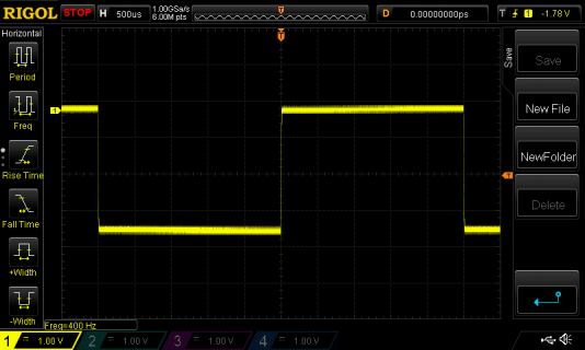
For 200 Hz I get a square signal, although somewhat noisy:

200Hz.png

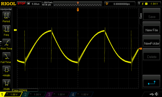
For 38 kHz, however, the signal doesn't even come close to a square wave:

38kHz.png

With the Arduino and the code in my original message, the 38 kHz signal is very clean!

Furthermore, in the IRremote library, in boarddefs.h one finds quite cryptic code for the Teensy LC:

Code:
// defines for TPM1 timer on Teensy-LC
#elif defined(IR_USE_TIMER_TPM1)
#define TIMER_RESET          FTM1_SC |= FTM_SC_TOF;
#define TIMER_ENABLE_PWM     CORE_PIN16_CONFIG = PORT_PCR_MUX(3)|PORT_PCR_DSE|PORT_PCR_SRE
#define TIMER_DISABLE_PWM    CORE_PIN16_CONFIG = PORT_PCR_MUX(1)|PORT_PCR_SRE
#define TIMER_ENABLE_INTR    NVIC_ENABLE_IRQ(IRQ_FTM1)
#define TIMER_DISABLE_INTR   NVIC_DISABLE_IRQ(IRQ_FTM1)
#define TIMER_INTR_NAME      ftm1_isr
#ifdef ISR
#undef ISR
#endif
#define ISR(f) void f(void)
#define TIMER_CONFIG_KHZ(val) ({                     \
	SIM_SCGC6 |= SIM_SCGC6_TPM1;                 \
	FTM1_SC = 0;                                 \
	FTM1_CNT = 0;                                \
	FTM1_MOD = (F_PLL/2000) / val - 1;           \
	FTM1_C0V = (F_PLL/6000) / val - 1;           \
	FTM1_SC = FTM_SC_CLKS(1) | FTM_SC_PS(0);     \
})
#define TIMER_CONFIG_NORMAL() ({                     \
	SIM_SCGC6 |= SIM_SCGC6_TPM1;                 \
	FTM1_SC = 0;                                 \
	FTM1_CNT = 0;                                \
	FTM1_MOD = (F_PLL/40000) - 1;                \
	FTM1_C0V = 0;                                \
	FTM1_SC = FTM_SC_CLKS(1) | FTM_SC_PS(0) | FTM_SC_TOF | FTM_SC_TOIE; \
})
#define TIMER_PWM_PIN        16

I've no idea what that means, but given my measurements, I doubt that using analogWriteFrequency is the way to go. What is the right approach?
 
Looks like no code problem, but the capacitative load on the output is large in relation to the switching speed and the current pin drive current.
 
I ran this code just now on a Teensy LC, with a IR LED and 100 ohm resistor connected to pin 3.

Code:
void setup() {
  const uint8_t pin = 3;
  analogWriteFrequency(pin, 38000);
  analogWrite(pin, 128); // for a 50:50 square wave
}

void loop() {
}

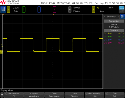
Here's the waveform I see:

file.png

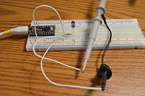
This is how I tested:

DSC_0495_web.jpg

I have no idea why you're getting that terrible waveform. Nothing like that happens when I try here. Maybe you could give some more detail about how you're doing the test?
 
Furthermore, in the IRremote library, in boarddefs.h one finds quite cryptic code for the Teensy LC:

I've no idea what that means, but given my measurements, I doubt that using analogWriteFrequency is the way to go. What is the right approach?
analogWriteFrequency() is the way to go. The IRremote library code for the LC sets the FTM timer either for PWM at given KHz (val) or sets the timer for 50us interrupt (for sampling IR input). The FTM PWM code mimics what the teensy core does for analogWriteFrequency() and analogWrite() with 33% duty.
core implementation in hardware/teensy/avr/cores/teensy3/pins_teensy.c

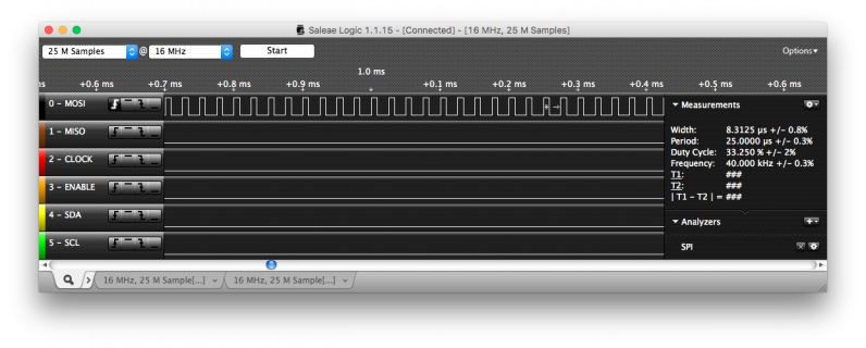
Here is logic analyzer plot of IRremote output pin on LC running the IRsendDemo example (40khz) (nothing but analyzer connected to output pin). If I zoom out on analyzer, I can see the Sony pulse encodings on the 40khz carrier.
z.png

With scope, signal is clean square wave (33% duty), with nothing attached to output pin except scope probe.
 
Last edited:
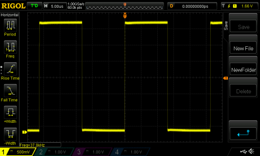
Now it works: :)

clean-38kHz.png

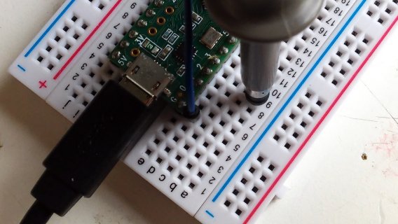
IMG_0148.jpg

Maybe there was a bad connection. As you can see, I connect the scope directly to ground and pin 3. I now moved the Teensy around on the breadboard and I changed wires. So I guess there was a bad connection, introducing some capacitance. I really don't know much about electronics. Therefore it was hard for me to single out the source of the problem. Thanks a lot for your patience!
 
Status
Not open for further replies.
Back
Top