Accessing SPI bus in Teensy 3.6

Status
Not open for further replies.
Hello all

I am new to the teensy world. Currently working the a 32 bit ADC (ProtoCentral ads1262 ) for more precision readings. It works using SPI protocol and I'm having issues accessing teensy 3.6 SPI bus. I am using Arduino SPI Library and it should be able to work with that right ?

I'm using pins 24,25,28 and 10 for PWDN, DRDY,START PIN and SS.
Also using 12,11 and 13 in Teensy for MOSI , MISO and SCK.

SPI.begin() is not enough because the code works perfectly fine in an Arduino Mega using its SPI but not with Teensy.

I'm confused a little here. It would be of great help if anyone can point me in the right direction.

Thanks in advance

Note : Attaching my codes too.
 

Attachments

  • ADC32bit_teensy.ino
    3.1 KB · Views: 282
  • adc1262.cpp
    4.2 KB · Views: 245
  • adc1262.h
    2.1 KB · Views: 199
Why would you use the Arduino SPI library instead of one which is known to be optimized and to work with Teensys, using their hardware SPI instead of bit banging?
 
In theory my library you mentioned should work. As well as the default SPI library that ships with Teensyduino.

Have you tried removing any version of the SPI library that is installed in your <Arduino sketch folder>/libraries/SPI and run it.
It would then grab the one that works from Teensyduino.

Also again it is hard to say as there is no information here on what is not working. So could be wiring issue, could be voltage issue... Could be software issue.

Example wiring, you say:
Also using 12,11 and 13 in Teensy for MOSI , MISO and SCK.
But on Teensy as well as many Arduino probably including mega: MOSI=11, MISO=12, SCK=13
So maybe pins reversed?

Not sure about power pins, sounds like you have some ranges of voltages which can work on it. But what voltage are you giving it? ... Again I only took a 10 second look at PDF for it. But the Vdd used I believe controls the voltages of any digital pins it uses... So hopefully 3.3v?

Code wise. The library you supplied is doing nothing fancy. However it using the old stuff for controlling SPI... That is it does:
Code:
void adc1262::adc1262_Init()
{
  SPI.begin();						// start the SPI library:
  SPI.setBitOrder(MSBFIRST); 	
  SPI.setDataMode(SPI_MODE1);				//CPOL = 0, CPHA = 1
  SPI.setClockDivider(SPI_CLOCK_DIV8); 	              //Selecting 1Mhz clock for SPI
...
Which I have not played with the setBotOrder, mode, clock divider calls for awhile now. So if I were using it I would do a 10 minute pass through your library and convert it to SPI transaction code.

That is I would probably remove those lines and use something like:
Code:
void adc1262::adc1262_Init()
{
  SPI.begin();						// start the SPI library:

  adc1262_Reset();
  delay(100);
  adc1262_Hard_Stop();
  delay(300);

  SPI.beginTransaction(SPISettings(1000000, MSBFIRST, SPI_MODE1));

  adc1262_Reg_Write(POWER,B0000000); 		// Internal reference voltage enabled
  delay(10);
  adc1262_Reg_Write(INTERFACE,B00000101);	//Status byte enabled , Checksum byte is checksum mode
  delay(10);
  adc1262_Reg_Write(MODE0, B00000000);		// Continous conversion mode, Input chop and IDAC rotation disabled
  delay(10);
  adc1262_Reg_Write(MODE1,10000000);		// FIR mode	
  delay(10);
  adc1262_Reg_Write(MODE2,B10000100);		//PGA disabled , PGA gain = 1v/v , Data rate =20SPS
  delay(10);
  adc1262_Reg_Write(INPMUX,B00000001);		//AINO and AIN1
  delay(10);  
  adc1262_Reg_Write(OFCAL0,B00000000);	
  delay(10);  
  adc1262_Reg_Write(OFCAL1,B00000000);	
  delay(10);  
  adc1262_Reg_Write(OFCAL2,B00000000);	
  delay(10);  
  adc1262_Reg_Write(FSCAL0,B00000000);	
  delay(10);  
  adc1262_Reg_Write(FSCAL1,B00000000);	
  delay(10);  
  adc1262_Reg_Write(FSCAL2,B01000000);	
  delay(10);  
  adc1262_Reg_Write(IDACMUX,0xBB);	
  delay(10);  
  adc1262_Reg_Write(IDACMAG,B00000000);	
  delay(10);  
  adc1262_Reg_Write(REFMUX,0x24);	
  delay(10);    
  adc1262_Reg_Write(TDACP,B00000000);	
  delay(10);    
  adc1262_Reg_Write(TDACN,B00000000);	
  delay(10);    
  adc1262_Reg_Write(GPIOCON,B00000000);	
  delay(10);    
  adc1262_Reg_Write(GPIODIR,B00000000);	
  delay(10);    
  adc1262_Reg_Write(GPIODAT,B00000000);	
  delay(10);    
  adc1262_Reg_Write(ADC2CFG,B00000000);	
  delay(10);    
  adc1262_Reg_Write(ADC2MUX,0x01);	
  delay(10);    
  adc1262_Reg_Write(ADC2OFC0, B00000000);	
  delay(10);    
  adc1262_Reg_Write(ADC2OFC1,B00000000);
  delay(10);
  adc1262_Reg_Write(ADC2FSC0, B00000000);	
  delay(10);    
  adc1262_Reg_Write(ADC2FSC1, 0x40);	
  delay(10);
  adc1262_Start_Data_Conv_Command ();
  delay(10);
  adc1262_Enable_Start();
  SPI.endTransaction();
}

I would also update the read data function as well.
Code:
char* adc1262::adc1262_Read_Data() // Read Data function
{
  SPI.beginTransaction(SPISettings(1000000, MSBFIRST, SPI_MODE1));
   static char SPI_Dummy_Buff[6];
   digitalWrite(ADC1262_CS_PIN, LOW);
	for (int i = 0; i < 6; ++i)
	{
		SPI_Dummy_Buff[i] = SPI.transfer(CONFIG_SPI_MASTER_DUMMY);	
	}
   digitalWrite(ADC1262_CS_PIN, HIGH);
  SPI.endTransaction();
	return SPI_Dummy_Buff;
}
If that did not work, I would then check the settings passed in, and maybe try different SPI_MODE and see if that made difference... I would also try higher speed, again my quick look at spec
it appears that SPI could run up to 8mhz...

Hopefully others can give more information
 
In theory my library you mentioned should work. As well as the default SPI library that ships with Teensyduino.

Have you tried removing any version of the SPI library that is installed in your <Arduino sketch folder>/libraries/SPI and run it.
It would then grab the one that works from Teensyduino.

Also again it is hard to say as there is no information here on what is not working. So could be wiring issue, could be voltage issue... Could be software issue.

Example wiring, you say:

But on Teensy as well as many Arduino probably including mega: MOSI=11, MISO=12, SCK=13
So maybe pins reversed?

Not sure about power pins, sounds like you have some ranges of voltages which can work on it. But what voltage are you giving it? ... Again I only took a 10 second look at PDF for it. But the Vdd used I believe controls the voltages of any digital pins it uses... So hopefully 3.3v?

Code wise. The library you supplied is doing nothing fancy. However it using the old stuff for controlling SPI... That is it does:
Code:
void adc1262::adc1262_Init()
{
  SPI.begin();						// start the SPI library:
  SPI.setBitOrder(MSBFIRST); 	
  SPI.setDataMode(SPI_MODE1);				//CPOL = 0, CPHA = 1
  SPI.setClockDivider(SPI_CLOCK_DIV8); 	              //Selecting 1Mhz clock for SPI
...
Which I have not played with the setBotOrder, mode, clock divider calls for awhile now. So if I were using it I would do a 10 minute pass through your library and convert it to SPI transaction code.

That is I would probably remove those lines and use something like:
Code:
void adc1262::adc1262_Init()
{
  SPI.begin();						// start the SPI library:

  adc1262_Reset();
  delay(100);
  adc1262_Hard_Stop();
  delay(300);

  SPI.beginTransaction(SPISettings(1000000, MSBFIRST, SPI_MODE1));

  adc1262_Reg_Write(POWER,B0000000); 		// Internal reference voltage enabled
  delay(10);
  adc1262_Reg_Write(INTERFACE,B00000101);	//Status byte enabled , Checksum byte is checksum mode
  delay(10);
  adc1262_Reg_Write(MODE0, B00000000);		// Continous conversion mode, Input chop and IDAC rotation disabled
  delay(10);
  adc1262_Reg_Write(MODE1,10000000);		// FIR mode	
  delay(10);
  adc1262_Reg_Write(MODE2,B10000100);		//PGA disabled , PGA gain = 1v/v , Data rate =20SPS
  delay(10);
  adc1262_Reg_Write(INPMUX,B00000001);		//AINO and AIN1
  delay(10);  
  adc1262_Reg_Write(OFCAL0,B00000000);	
  delay(10);  
  adc1262_Reg_Write(OFCAL1,B00000000);	
  delay(10);  
  adc1262_Reg_Write(OFCAL2,B00000000);	
  delay(10);  
  adc1262_Reg_Write(FSCAL0,B00000000);	
  delay(10);  
  adc1262_Reg_Write(FSCAL1,B00000000);	
  delay(10);  
  adc1262_Reg_Write(FSCAL2,B01000000);	
  delay(10);  
  adc1262_Reg_Write(IDACMUX,0xBB);	
  delay(10);  
  adc1262_Reg_Write(IDACMAG,B00000000);	
  delay(10);  
  adc1262_Reg_Write(REFMUX,0x24);	
  delay(10);    
  adc1262_Reg_Write(TDACP,B00000000);	
  delay(10);    
  adc1262_Reg_Write(TDACN,B00000000);	
  delay(10);    
  adc1262_Reg_Write(GPIOCON,B00000000);	
  delay(10);    
  adc1262_Reg_Write(GPIODIR,B00000000);	
  delay(10);    
  adc1262_Reg_Write(GPIODAT,B00000000);	
  delay(10);    
  adc1262_Reg_Write(ADC2CFG,B00000000);	
  delay(10);    
  adc1262_Reg_Write(ADC2MUX,0x01);	
  delay(10);    
  adc1262_Reg_Write(ADC2OFC0, B00000000);	
  delay(10);    
  adc1262_Reg_Write(ADC2OFC1,B00000000);
  delay(10);
  adc1262_Reg_Write(ADC2FSC0, B00000000);	
  delay(10);    
  adc1262_Reg_Write(ADC2FSC1, 0x40);	
  delay(10);
  adc1262_Start_Data_Conv_Command ();
  delay(10);
  adc1262_Enable_Start();
  SPI.endTransaction();
}

I would also update the read data function as well.
Code:
char* adc1262::adc1262_Read_Data() // Read Data function
{
  SPI.beginTransaction(SPISettings(1000000, MSBFIRST, SPI_MODE1));
   static char SPI_Dummy_Buff[6];
   digitalWrite(ADC1262_CS_PIN, LOW);
	for (int i = 0; i < 6; ++i)
	{
		SPI_Dummy_Buff[i] = SPI.transfer(CONFIG_SPI_MASTER_DUMMY);	
	}
   digitalWrite(ADC1262_CS_PIN, HIGH);
  SPI.endTransaction();
	return SPI_Dummy_Buff;
}
If that did not work, I would then check the settings passed in, and maybe try different SPI_MODE and see if that made difference... I would also try higher speed, again my quick look at spec
it appears that SPI could run up to 8mhz...

Hopefully others can give more information

Thank you so much ... Will try and let you know
 
Still No help

I tried changing code a bit here and there bit still no success. I will just tell what I want to do !

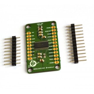
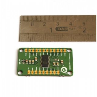
I got this 32 bit ADC (works with SPI protocol ) : protocentral-ads1262-32-bit-precision-adc-breakout-board.jpg
https://www.protocentral.com/analog-adc-boards/1005-protocentral-ads1262-32-bit-precision-adc-breakout-board-0642078949630.html

The code gives me the analog voltage difference between pins AIN1 and AIN0 using Arduino.

But now i'm planning to shift to Teensy and I want to use the same code and get the voltage difference. I tried using Teensy default SPI Library as well KurTE's code but im getting output as
0.000000 , irrespective of whatever voltage difference.

Tried with SPI0 and SPI1 bus in teensy but to no help. I think the code is doing something because the whatever o/p i get ( 0.0000 only ) , its very slow like 5-10 values in a minute. Kinda a bit confused and stuck here .Double checked my wiring's and connections which are absolutely fine.

Please help to find my error and fix it.
 

Attachments

  • protocentral-ads1262-32-bit-precision-adc-breakout-board.jpg
    protocentral-ads1262-32-bit-precision-adc-breakout-board.jpg
    74 KB · Views: 231
  • adc1262.h
    2.1 KB · Views: 145
  • ADC32bit_teensy.ino
    3.1 KB · Views: 115
  • adc1262.cpp
    4.2 KB · Views: 165
Again sorry I don't have this device so can not help to much more.

But if it were me, I would sprinkle more debug code in your INO file to get an idea what is happening.

Did the Initialized successfully... message print?

Maybe add a print statement in the if((digitalRead(ADC1262_DRDY_PIN)) == LOW) block to see if this state is happening.
Maybe print out the the SPI_RX_Buff_Ptr... Maybe print out the bytes that are retrieved...

Maybe in library move the SPI_Dummy_Buff out of subroutine and make global... ...
Again hard to debug without the hardware...

Again when you said you tried SPI1... I assume you edited the library to move all references From SPI. to SPI1.

I assume you are using default IO SPI pins...

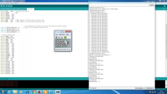
After some debug using serial.print() , I believe the problem is with the SPI1.transfer() function. Used a uint8_t flag with the SPI1.transfer() function and I'm getting 0xF which indicates that transfer was not successful. Not sure why it works well with arduino and its spi library library and not with teensy.

What could be the possible issues which results in failure of spi1.transfer() ? The connections are all correct and it works perfectly fine with arduino too , so just struggling to find a way . I had a look into the spi.transfer() function in the spi.h file ( for teensy 3.5/3.6 ) and placed a serial.print() to know whether it was getting executed and that was positive. That function is not writing the data to the device the way I want and I believe that's why the device is responding with 0.000.

What should I try to do as my next step ?

thanks in advance for your time..
 
How are you powering the device ? data sheet seems to say it wants 5v for analog power supply, though digital supply can be 2.7 to 5v. The T3.6 is not 5v tolerant, so you would need level shifters for SPI pins if you are powering device at 5v

The Arduino Mega is 5v so that is cool, but you may have damaged T3.6 if device was using only 5v.
 
Last edited:
Sorry again not sure what you mean used a uint8_flag with SPI1.transfer() function and it returned 0xf as not successful . When you do a x=SPI1.transfer(y);
What happens is the y value is shifted out the MOSI1 pin Default pin 0, and whatever is seen on the MISO1 pin (default pin 1) is returned... and SCK1 pin default pin 32 is the clock pin.

Again picture showing connections and actual code would help. Like if you used SPI1 transfer. What Pins are you connected up to? How are you making the connections? With breadboard? If so are the Pins soldered into Teensy?
 
if you have a 3.3v SPI device handy, you could confirm your T3.6/SPI is still working. Or run this loopback sketch with a jumper between MISO and MOSI.
Code:
// SPI loopback check, jumper MOSI to MISO
#include <SPI.h>
void setup() {
  Serial.begin(9600);
  SPI.begin();
}

void loop() {
  int i,errs=0;
  uint8_t buff[32];

  for(i=0;i<sizeof(buff); i++) buff[i]=i;
  SPI.beginTransaction(SPISettings(4000000, MSBFIRST, SPI_MODE0));
  SPI.transfer(buff,sizeof(buff));
  SPI.endTransaction();
  for(i=0;i<sizeof(buff); i++) if (buff[i]!=i) errs++;
  Serial.print("errs "); Serial.println(errs);
  delay(2000);
}

with nothing connected to SPI pins, you should get 32 errors. With MOSI-MISO jumper, hopefully reports 0 errors
 
How are you powering the device ? data sheet seems to say it wants 5v for analog power supply, though digital supply can be 2.7 to 5v. The T3.6 is not 5v tolerant, so you would need level shifters for SPI pins if you are powering device at 5v

The Arduino Mega is 5v so that is cool, but you may have damaged T3.6 if device was using only 5v.


Teensy Vin pin gives me an output voltage of 5 volts. That power my device and my teensy 3.6 is working as I checked with other sensors.
 
Sorry again not sure what you mean used a uint8_flag with SPI1.transfer() function and it returned 0xf as not successful . When you do a x=SPI1.transfer(y);
What happens is the y value is shifted out the MOSI1 pin Default pin 0, and whatever is seen on the MISO1 pin (default pin 1) is returned... and SCK1 pin default pin 32 is the clock pin.

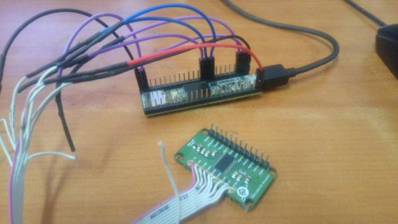
Again picture showing connections and actual code would help. Like if you used SPI1 transfer. What Pins are you connected up to? How are you making the connections? With breadboard? If so are the Pins soldered into Teensy?


The pin connections are as :

ADC_PINS Teensy SPI0 Bus Teensy SPI1 Bus
5v Vin Pin Vin Pin
GND GND GND
PWDN 7 7
DRDY 8 8
MISO 12 1
MOSI 11 0
SCK 13 32
CS 10 31
START 9 9

I just added this piece of code to my adc library
uint8_t flag=SPI1.transfer(data_in);
Serial.print(flag);
Serial.println(" : Entering the SPI Command Data");

My idea was whatever is seen on the MISO1 pin that is returned shouldn't depend on the controller. Using the Teensy 3.6 SPI1 bus I'm getting the same return values at both arduino and teensy. The code should give the analog voltage difference between AIN0 and AIN1 of the ADVC. It works well with an arduino but when uploaded to Teensy the ADC value im getting is '0' but the weird thing is that the rate at which the output is displayed is very slow. Its like one value at every 15 seconds which should not be the case . My intuition is that the ADC is getting timed out or the commands are not properly transferred from Teensy to the ADC .

Rignt now im trying to figure what data is send to the MOSI and MISO pins using a bus pirate just to make sure that the commands are atleast written to the ADC.

Connection diagram and source are uploaded.

Thank you in advance for your time:

Untitled.jpg connections.jpg


View attachment teensy_test.ino View attachment adc1262.h View attachment SPI.cpp View attachment SPI.h View attachment adc1262.cpp
 
Last edited:
EDIT: ooops, those were SPI1 alternate pins, you're using correct SPI1 pins

of concern, the T3.6 does NOT have 5v tolerant data pins, but your ADC device is being powered at 5v. you need level shifters to protect your T3.6/SPI pins (MISO). T3.5 does have 5v-tolerant data pins.
 
Last edited:
if you have a 3.3v SPI device handy, you could confirm your T3.6/SPI is still working. Or run this loopback sketch with a jumper between MISO and MOSI.
Code:
// SPI loopback check, jumper MOSI to MISO
#include <SPI.h>
void setup() {
  Serial.begin(9600);
  SPI.begin();
}

void loop() {
  int i,errs=0;
  uint8_t buff[32];

  for(i=0;i<sizeof(buff); i++) buff[i]=i;
  SPI.beginTransaction(SPISettings(4000000, MSBFIRST, SPI_MODE0));
  SPI.transfer(buff,sizeof(buff));
  SPI.endTransaction();
  for(i=0;i<sizeof(buff); i++) if (buff[i]!=i) errs++;
  Serial.print("errs "); Serial.println(errs);
  delay(2000);
}

with nothing connected to SPI pins, you should get 32 errors. With MOSI-MISO jumper, hopefully reports 0 errors

Thanks man ..that was helpful ..but just one doubt

How can I access teensy spi0 bus ( MOSI0 , MISO0 and sck0 ) ?
 
Thanks man ..that was helpful ..but just one doubt

How can I access teensy spi0 bus ( MOSI0 , MISO0 and sck0 ) ?

I'm not sure i understand. SPI.begin() is using SPI0 (default SCK0/MOSI0/MISO0 are pins 13/11/12), see reference card that comes with Teensy or
https://www.pjrc.com/teensy/pinout.html

EDIT: you could change the loopback sketch above to use SPI1 and jumper MOSI1/MISO1 (0/1) to see if SPI1 pins are still working. But even if loopback test worked, T3.6 could still be damaged from the 5v (e.g. the data-ready pin). So you may need to buy a T3.5

https://forum.pjrc.com/threads/39060-Well-duh-the-Teensy-3-6-is-NOT-5v-tolerant
 
Last edited:
EDIT: ooops, those were SPI1 alternate pins, you're using correct SPI1 pins

of concern, the T3.6 does NOT have 5v tolerant data pins, but your ADC device is being powered at 5v. you need level shifters to protect your T3.6/SPI pins (MISO). T3.5 does have 5v-tolerant data pins.


Thanks man ..Got Teensy 3.5 today. Let me check it out with 3.5 today.
 
I'm not sure i understand. SPI.begin() is using SPI0 (default SCK0/MOSI0/MISO0 are pins 13/11/12), see reference card that comes with Teensy or
https://www.pjrc.com/teensy/pinout.html

EDIT: you could change the loopback sketch above to use SPI1 and jumper MOSI1/MISO1 (0/1) to see if SPI1 pins are still working. But even if loopback test worked, T3.6 could still be damaged from the 5v (e.g. the data-ready pin). So you may need to buy a T3.5

Got teensy 3.5 .

If we use SPI.begin() it wont make use the default SCK0/MOSI0/MISO0 are pins 13/11/12 . I had a look into the Teensy SPI.cpp code and SPI.begin() fucntion call will invoke the class for 32 bit Teensy 3.0 and 3.1 , not the 3.5/3.6 one.
 
If we use SPI.begin() it wont make use the default SCK0/MOSI0/MISO0 are pins 13/11/12 . I had a look into the Teensy SPI.cpp code and SPI.begin() fucntion call will invoke the class for 32 bit Teensy 3.0 and 3.1 , not the 3.5/3.6 one.


? Yep, it does. Run the loopback sketch above and jumper pin 11 to 12. SPI.begin() is using MOSI0/MISO0 (11/12)
 
? Yep, it does. Run the loopback sketch above and jumper pin 11 to 12. SPI.begin() is using MOSI0/MISO0 (11/12)

Thats where I am getting confused . The loopback sketch gives me error 0 which should indicate that the SPI bus in working. But i did some debugging in the spi.cpp and spi.h files ( since my spi device was not working the default SCK0/MOSI0/MISO0 ) and got me into following conclusions.

the SPI.beginTransaction() function executes the function for 32 bit teensy 3.0/3.1's beginTranscation function.
and the SPI.tansfer() is not calling any function at all..

Kinda a bit confused here..
 
I'm not sure why you need to be looking at library files SPI.h and SPI.cpp, but note there are two versions of SPI lib, the Teensy version is
hardware/teensy/avr/libraries/SPI/SPI.*

Do you have a scope or logic analyzer to observe the SPI pins in action? Does device still work on mega2560?
If you look at datasheet or the device library, can you test a simple SPI transaction that reads back data from the device?
Recheck your wire connections...
 
Not sure what you are saying here. The simple transfer function is inlined in the spi.h file (or on my version spikinetis.h), where it checks the status register, then uses a PUSHR register and then loops waiting for it to complete where it then pops the data off using the POPR register...
 
If you look at datasheet or the device library, can you test a simple SPI transaction that reads back data from the device?
Recheck your wire connections...

Here is a sketch that should read the first 6 registers (bytes) of the ADS1262 (though I don't have a device to actually test with). Also your .cpp is using SPI MODE0, the drivers on the web and datasheet say you should be using MODE1. sketch does compile and print 0s with nothing connected to SPI pins.
Code:
#include <SPI.h>
#include "adc1262.h"

#define PGA 1                        	// Programmable Gain = 1
#define VREF 5             	      	 
#define VFSR VREF/PGA             
#define FSR (((long int)1<<23)-1)  

adc1262 ADC1262_1; 				// Class member
float output_pin=3;

double volt_V=0;
double volt_mV=0;
volatile int i;
volatile char SPI_RX_Buff[10];
volatile long adc1262_rx_Data[10];
volatile static int SPI_RX_Buff_Count = 0;
volatile char *SPI_RX_Buff_Ptr;
volatile int Responsebyte = false;
volatile signed long sads1262Count = 0;
volatile signed long uads1262Count=0;
double resolution;

#define SPIx SPI

void setup() 
{
  Serial.begin(115200);
  while(!Serial);
  SPIx.begin();
  // initalize the  data ready and chip select pins:
  pinMode(ADC1262_DRDY_PIN, INPUT);                  //data ready input line
  pinMode(ADC1262_CS_PIN, OUTPUT);                   //chip enable output line
  pinMode(ADC1262_START_PIN, OUTPUT);               // start 
  pinMode(ADC1262_PWDN_PIN, OUTPUT);                // Power down output   
  
  pinMode(output_pin, OUTPUT);

  //initalize ADS1262 slave
  ADC1262_1.adc1262_Init();                      // initialise ads1262
  Serial.println("adc1262 Initialised successfully....");
  SPIx.beginTransaction(SPISettings(1000000, MSBFIRST, SPI_MODE1));
  digitalWrite(ADC1262_CS_PIN, LOW);
  SPIx.transfer(0x20);   // read reg 0
  SPIx.transfer(5);      // read 6 bytes
  for (int i=0;i<6;i++) {
  	uint8_t b = SPIx.transfer(0xff);
	Serial.println(b,HEX);
  }
  digitalWrite(ADC1262_CS_PIN, HIGH);
  SPIx.endTransaction();

 }

void loop() 
{}


Tried ..Not working .. Just zero's !! ...each byte is Zero..
Something is wrong and I cannot identify it !!

Thanks for your time man !!
 
Something is wrong and I cannot identify it !!

Maybe a wire isn't connected properly? I see the earlier photo looks like wiring for SPI1. You're changed things for normal SPI, right? If you're stuck, post another photo of the wires, or several photos so we can really see.
 
Status
Not open for further replies.
Back
Top