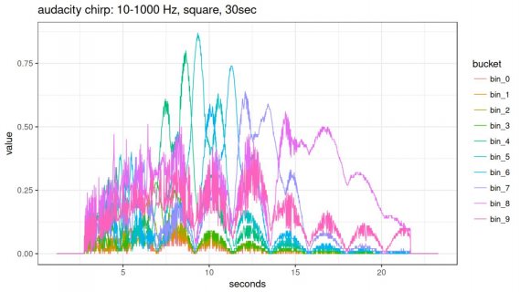
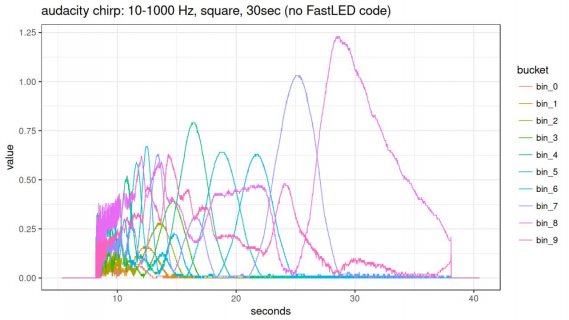
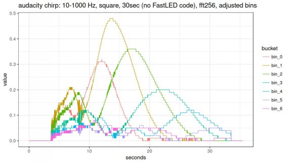
I wasn't sure how to title this. I have an LED 16x16 matrix and I'm trying to create a simple spectrum analyzer/reactive music visualization. I thought it was working (lights more or less "bounce" with the music), but when really listening for high/low and watching where the action was, I got the sense that something wasn't right. I used audacity to send a min-max frequency (10-1000 Hz in this case) sine and square wave over 30sec and now see that the thing is pretty much haphazard.
I replicated the circuit that pops up for the adc input at the audio library design tool. I'm essentially replicating the AudioSpectrumAnalyzerBasic code, other than adding the mapping from a frequency level to some number of LEDs to light up. I'm using a teensy 3.2, and it's hard to capture, but pictures to examine my wiring can be found here.
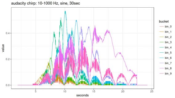
To illustrate the behavior, here's a youtube video showing the LED strips lighting up during the test (bottom is level[0], top is level[15]). The also contains the output of the fft.read(min, max) plotted over the span of the audacity chirps; I was worried about embedding as some forums care about size... I see they're scaled anyway, so here you are:
sine:
square:
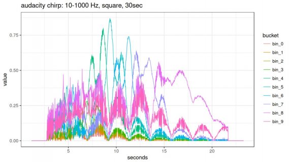
This was collected via the serial monitor, and since I'm going to 1000 Hz and using AudioAnalyzeFFT1024, I did 1000/47 to see that this should only light up to ~fft.read(21), which is in my level[8]. There's activity all the way up to level[15], but plotting curves by color isn't great when using so many bins so I reduced to level[0] through level[9] for plotting.
It's hard to know how to hunt for this, but I found this post where the suggestion was made to short audio input to gnd. I did that and get all 0's.
I'm have essentially zero audio circuit knowledge, so I have no idea what to even look for! At one point I tried adding capacitors in parallel to create 20-40 uF values instead of the example circuit 10uF value, but that didn't create any noticeable differences.
Thanks for taking a look!
----------
Here's the code:
I replicated the circuit that pops up for the adc input at the audio library design tool. I'm essentially replicating the AudioSpectrumAnalyzerBasic code, other than adding the mapping from a frequency level to some number of LEDs to light up. I'm using a teensy 3.2, and it's hard to capture, but pictures to examine my wiring can be found here.
To illustrate the behavior, here's a youtube video showing the LED strips lighting up during the test (bottom is level[0], top is level[15]). The also contains the output of the fft.read(min, max) plotted over the span of the audacity chirps; I was worried about embedding as some forums care about size... I see they're scaled anyway, so here you are:
sine:

square:

This was collected via the serial monitor, and since I'm going to 1000 Hz and using AudioAnalyzeFFT1024, I did 1000/47 to see that this should only light up to ~fft.read(21), which is in my level[8]. There's activity all the way up to level[15], but plotting curves by color isn't great when using so many bins so I reduced to level[0] through level[9] for plotting.
It's hard to know how to hunt for this, but I found this post where the suggestion was made to short audio input to gnd. I did that and get all 0's.
I'm have essentially zero audio circuit knowledge, so I have no idea what to even look for! At one point I tried adding capacitors in parallel to create 20-40 uF values instead of the example circuit 10uF value, but that didn't create any noticeable differences.
Thanks for taking a look!
----------
Here's the code:
Code:
#define FASTLED_ALLOW_INTERRUPTS 0
#define ADC_INPUT_PIN   A2

// all these libraries are required for the Teensy Audio Library
#include <FastLED.h>
#include <SD.h>
#include <SPI.h>
#include <Wire.h>
#include <Audio.h>

// fast led constants and initialize
#define DATA_PIN    22
#define LED_TYPE    WS2812B
#define COLOR_ORDER GRB
#define NUM_LEDS    256
CRGB leds[NUM_LEDS];

AudioInputAnalog         input(ADC_INPUT_PIN);
AudioAnalyzeFFT1024      fft;
AudioConnection          audioConnection(input, 0, fft, 0);

// An array to hold the 16 frequency bands
float level[16];

// this hardly does anything for debug;
// in real practice I create reactive scaling to watch for the
// highest frequency seen per level[i] and use this to various levels
// from always maxing out as it's hard to know per-song which
// bins will be hotter
float cur_max[16];

int hue = 0;
int delta = 3;
int bright = 255;
int sat = 255;
int fill = 0;

void setup()
{
    Serial.begin(9600);

    FastLED.addLeds<LED_TYPE, DATA_PIN, COLOR_ORDER>(leds, NUM_LEDS);
    FastLED.setBrightness(60);

    // Audio requires memory to work.
    AudioMemory(12);

    // for debug, I set each bin to 400 and leave it
    // normally I'd replace with the max per bin seen as the audio streams
    for(int i = 0; i < 16; i++) { cur_max[i] = 400; }
}

void loop()
{

    if (fft.available())
    {

      level[0] = fft.read(2);
      level[1] = fft.read(3);
      level[2] = fft.read(4);
      level[3] = fft.read(5);
      level[4] = fft.read(6, 7);
      level[5] = fft.read(8, 9);
      level[6] = fft.read(10, 11);
      level[7] = fft.read(12, 14);
      level[8] = fft.read(15, 23);
      level[9] = fft.read(24, 38);
      level[10] = fft.read(39, 59);
      level[11] = fft.read(60, 75);
      level[12] = fft.read(75, 89);
      level[13] = fft.read(90, 111);
      level[14] = fft.read(112, 163);
      level[15] = fft.read(164, 375);


      // troubleshooting printing
      Serial.print(millis());

      for(int i = 0; i < 16; i ++)
      {

      	Serial.print(",");
        Serial.print(level[i]);

      }

      Serial.println();


      //// main eq section
      for(int i = 0; i < 16; i++)
      {

        fill = constrain(map(level[i] * 1000, 30, int(cur_max[i]), 0, 16), 0, 16);
        fill_solid(leds + (i*16), fill, CHSV(i*220/16, 255, 255));

      }

      FastLED.show();

    } // if()

    EVERY_N_MILLISECONDS(10) { fadeToBlackBy(leds, 256, 25); }

  } // loop()
Last edited:


